
User`s manual


Introduction 17
PCIe-2602
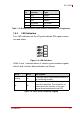
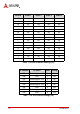
Table 1-11: D I/O Switch Settings (S5)
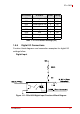
1.5.6 Digital I/O Connections
Function block diagrams and connection examples for digital I/O
settings follow.
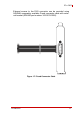
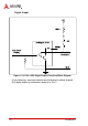
Digital Input
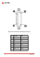
Figure 1-11: PCIe-2602 Digital Input Functional Block Diagram
DI Channel DI Status Slider Setting
DO0 Pulled high to +5V 1 On
DO0 Low 1 Off
DO1 Pulled high to +5V 2 On
DO1 Low 2 Off
DO2 Pulled high to +5V 3 On
DO2 Low 3 Off
DO3 Pulled high to +5V 4 On
DO3 Low 4 Off