
User`s manual


Introduction 13
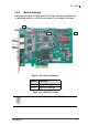
PCIe-2602
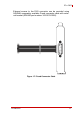
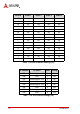
Table 1-5: D-sub Connector Cable Exterior Connector Pin Assignments
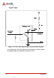
1.5.4 LED Indicators
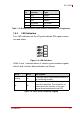
Four LED indicators on the I/O panel indicate SDI signal connec-
tion and status.
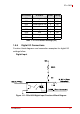
Figure 1-9: LED Indicators
LEDs 0 and 1 indicate status of vertical synchronization signals,
while 2 and 3 confirm data verification, as follows.
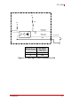
Table 1-6: LEDs 0 and 2 Indicator Legend
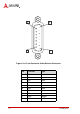
6 DO1 Output
14 GND DO Ground
7 DO2 Output
15 DO clamp DO Power
8 DO3 Output
LED 0 LED 2 Description
Blinking On
The input signal is identified and channel 0
is functioning normally
Off Off
No input is detected or the input signal
cannot be identified. The connection or
cable should be checked, or the input
signal format determined to be SDI.
Pin Function Type