
User`s manual

8 Introduction
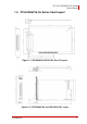
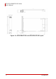
PCI/cPCI-6208/6216-GL Series
User’s Manual
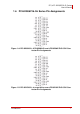
The analog output pin are specified as Vn and A.GND, where:
Vn: The voltage output of channel number n.
Z For PCI-6208V-GL, cPCI-6208V-GL and cPCI-6208V/R-
GL, n = 0 to 7
Z For PCI-6216V-GL, cPCI-6216V-GL and cPCI-6216V/R-
GL, n = 0 to 15
A.GND: The ground pin of analog output. All ground pins are
tied together.
The digital input and output pin names are specified as DIn and
DOn respectively, where n = 0 to 3.
1.7 Termination Boards and Cables
PCI-6208/6216-GL Series cards are equipped with a 37-pin D-
sub connector and compatible with the following termination
boards..
X DIN-37D-01: A general purposed 37-pin screw terminal with
a DIN-socket (cables are not included).
X ACLD-9137-01: General-Purpose termination board with a
37-pin D-sub male connector.
X ACLD-9138-01: General-Purpose termination board with a
37-pin D-sub connector.
X ACL-10137: 37-pin D-Sub male-male cable.