
User`s manual

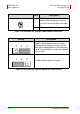
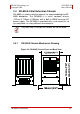
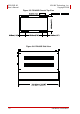
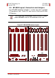


Table Of Contents
- ECS-8582-4S
- Revision History
- Preface
- Table of Contents
- List of Figures
- List of Tables
- 1 Introduction
- 2 Getting Started
- 3 Hardware Information
- 3.1 Functional Block Diagram
- 3.2 EC-8560
- 3.3 PCI-8565 Layout, Connectors and Jumpers
- 3.4 RK-8005 4-Slot Extension Chassis
- 3.5 BP-8005 Layout, Connectors and Jumpers
- Figure 3-7: BP-8005 Backplane Layout
- Table 3-4: BP-8005 Connectors, Jumpers and LED
- Table 3-5: BP-8005 CN1 LED Connector
- Table 3-6: BP-8005 CN2 ATX Power Connector
- Table 3-7: BP-8005 CN3 Fan Connector
- Table 3-8: BP-8005 CN4 ATX Power OK Status Connector
- Table 3-9: BP-8005 JP1 LED Connector
- Table 3-10: BP-8005 JP2 ATX Power Enable Connector
- Table 3-11: BP-8005 JP3 Fan Connector
- 3.6 Extension Cable Options
- 4 Troubleshooting (FAQ)
- Important Safety Instructions
- Warranty Policy
Hardware Information 25
ADLINK Technology, Inc. ECS-8582-4S
Copyright 2008 User’s Manual
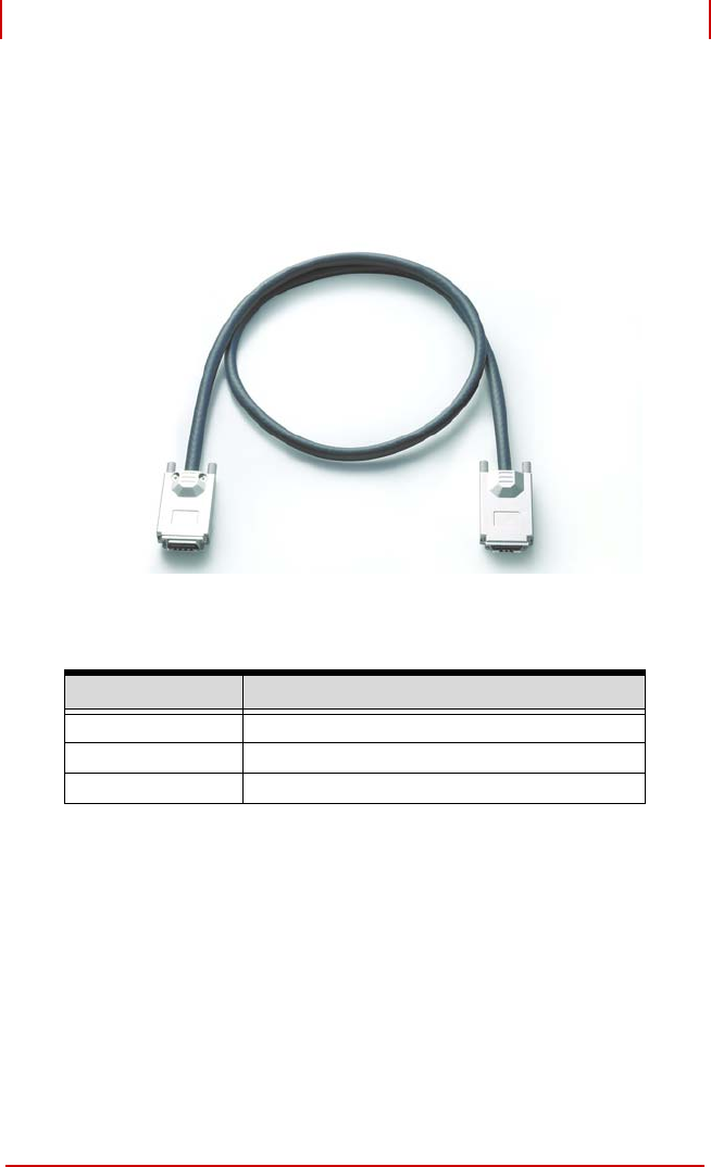
3.6 Extension Cable Options
The PCI Express
®
-to-PCI extension system (PCES-8581-13S and
PCES-8581-4S) is available with three different cables in length.
These cables are designed to transfer high speed signals and
have high immunity from electromagnetic interference.
Figure 3-8: Standard 3 M extension cable (ALC-PCEEXT-3)
Part Number Description
ACL-EXPRESS-1 1 M, PCI Express-to-PCI extension cable
ACL-EXPRESS-3 3 M, PCI Express-to-PCI extension cable
ACL-EXPRESS-7 7 M, PCI Express-to-PCI extension cable
Table 3-12: Optional Extension Cables