
User`s manual

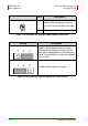
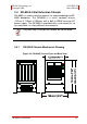
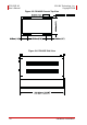
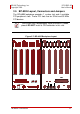


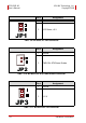

Table Of Contents
- ECS-8582-4S
- Revision History
- Preface
- Table of Contents
- List of Figures
- List of Tables
- 1 Introduction
- 2 Getting Started
- 3 Hardware Information
- 3.1 Functional Block Diagram
- 3.2 EC-8560
- 3.3 PCI-8565 Layout, Connectors and Jumpers
- 3.4 RK-8005 4-Slot Extension Chassis
- 3.5 BP-8005 Layout, Connectors and Jumpers
- Figure 3-7: BP-8005 Backplane Layout
- Table 3-4: BP-8005 Connectors, Jumpers and LED
- Table 3-5: BP-8005 CN1 LED Connector
- Table 3-6: BP-8005 CN2 ATX Power Connector
- Table 3-7: BP-8005 CN3 Fan Connector
- Table 3-8: BP-8005 CN4 ATX Power OK Status Connector
- Table 3-9: BP-8005 JP1 LED Connector
- Table 3-10: BP-8005 JP2 ATX Power Enable Connector
- Table 3-11: BP-8005 JP3 Fan Connector
- 3.6 Extension Cable Options
- 4 Troubleshooting (FAQ)
- Important Safety Instructions
- Warranty Policy
22 Hardware Information
ECS-8582-4S ADLINK Technology, Inc.
User’s Manual Copyright 2008
Table 3-4: BP-8005 Connectors, Jumpers and LED
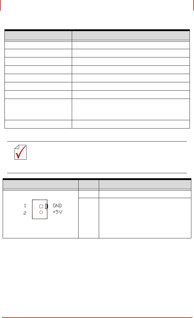
Table 3-5: BP-8005 CN1 LED Connector
Connector/Jumper/LED Description
CN1 LED connector
CN2 ATX power connector
CN3 Fan connector
CN4 ATX power OK status connector
JP1 LED connector
JP2 ATX power enabler
JP3 Fan connector
System
System slot for extension card. This slot is modi-
fied for bus extension purposes and does not
support general signal board controllers.
PCI1 to PCI4 Peripheral PCI Slot
NOTE:
NOTE:
DO NOT plug CPU cards in the system slot.
Pin # Assignment
1 Ground
2 +5 V Output
CN1