
User`s manual

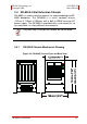
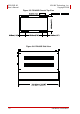
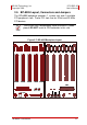


Table Of Contents
- ECS-8582-4S
- Revision History
- Preface
- Table of Contents
- List of Figures
- List of Tables
- 1 Introduction
- 2 Getting Started
- 3 Hardware Information
- 3.1 Functional Block Diagram
- 3.2 EC-8560
- 3.3 PCI-8565 Layout, Connectors and Jumpers
- 3.4 RK-8005 4-Slot Extension Chassis
- 3.5 BP-8005 Layout, Connectors and Jumpers
- Figure 3-7: BP-8005 Backplane Layout
- Table 3-4: BP-8005 Connectors, Jumpers and LED
- Table 3-5: BP-8005 CN1 LED Connector
- Table 3-6: BP-8005 CN2 ATX Power Connector
- Table 3-7: BP-8005 CN3 Fan Connector
- Table 3-8: BP-8005 CN4 ATX Power OK Status Connector
- Table 3-9: BP-8005 JP1 LED Connector
- Table 3-10: BP-8005 JP2 ATX Power Enable Connector
- Table 3-11: BP-8005 JP3 Fan Connector
- 3.6 Extension Cable Options
- 4 Troubleshooting (FAQ)
- Important Safety Instructions
- Warranty Policy
Hardware Information 19
ADLINK Technology, Inc. ECS-8582-4S
Copyright 2008 User’s Manual
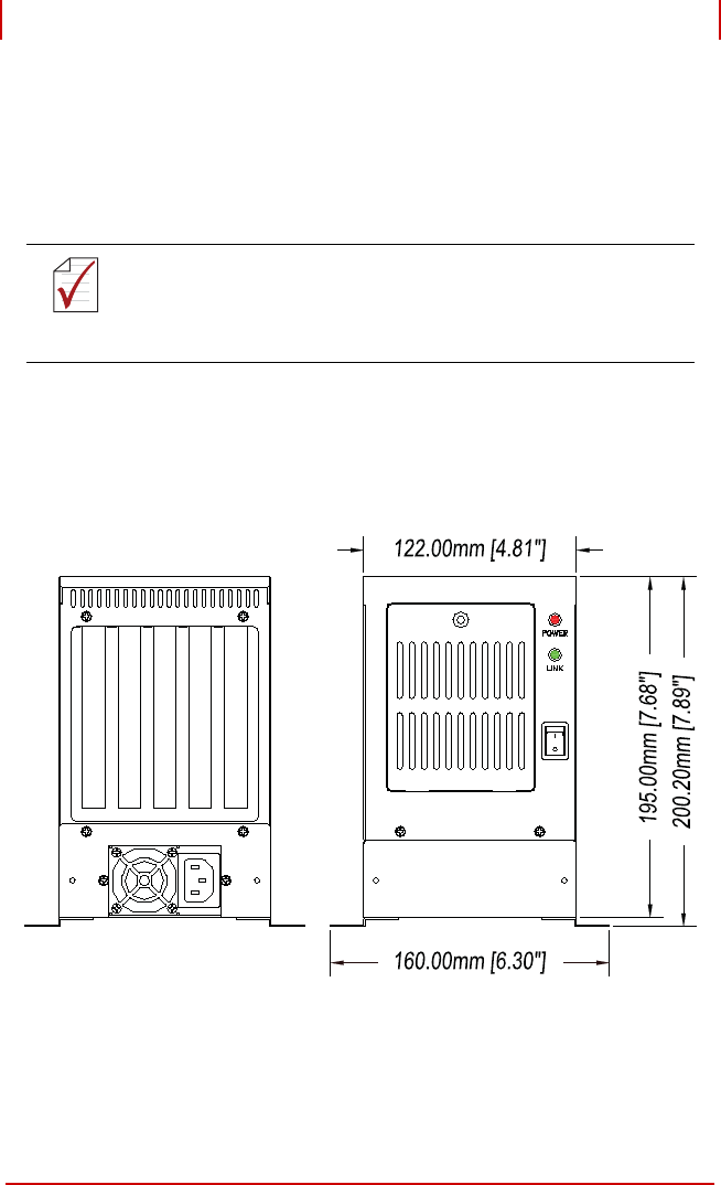
3.4 RK-8005 4-Slot Extension Chassis
RK-8005 is a robust industrial chassis for accommodating the BP-
8005 backplane. The RK-8005 is a small, compact chassis
(122mm X 195mm X 260mm) with a built-in 200W universal AC
power supply. The RK-8005 is provided with a wall-mount kit so
you can place it in many different environments.
3.4.1 RK-8005 Chassis Mechanical Drawing
Figure 3-4: RK-8005 Chassis Front and Back View
NOTE:
NOTE:
Only half-size PCI cards are suitable for the RK-8005.