
User`s manual

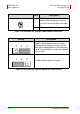
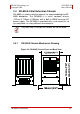
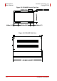
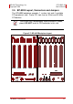


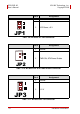


Table Of Contents
- ECS-8582-4S
- Revision History
- Preface
- Table of Contents
- List of Figures
- List of Tables
- 1 Introduction
- 2 Getting Started
- 3 Hardware Information
- 3.1 Functional Block Diagram
- 3.2 EC-8560
- 3.3 PCI-8565 Layout, Connectors and Jumpers
- 3.4 RK-8005 4-Slot Extension Chassis
- 3.5 BP-8005 Layout, Connectors and Jumpers
- Figure 3-7: BP-8005 Backplane Layout
- Table 3-4: BP-8005 Connectors, Jumpers and LED
- Table 3-5: BP-8005 CN1 LED Connector
- Table 3-6: BP-8005 CN2 ATX Power Connector
- Table 3-7: BP-8005 CN3 Fan Connector
- Table 3-8: BP-8005 CN4 ATX Power OK Status Connector
- Table 3-9: BP-8005 JP1 LED Connector
- Table 3-10: BP-8005 JP2 ATX Power Enable Connector
- Table 3-11: BP-8005 JP3 Fan Connector
- 3.6 Extension Cable Options
- 4 Troubleshooting (FAQ)
- Important Safety Instructions
- Warranty Policy
18 Hardware Information
ECS-8582-4S ADLINK Technology, Inc.
User’s Manual Copyright 2008
Pin # Assignment
1
PWR-ON. This pin is used for remote
power-on/off functionality. Connect
this to JP2 on the BP-8014 to enable
it.
2N/C
Table 3-2: PCI-8565 JP1 Remote Power-ON/Off Connector
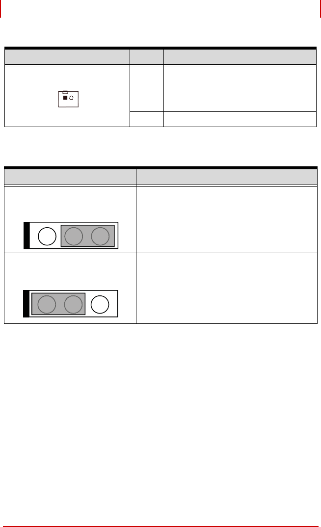
Setting Description
Enables spread spectrum control. When
enabling spread spectrum control, the PCI
clock will be modulated with a low frequency
carrier, the peak EMI can be greatly reduced
in the system.
Disables spread spectrum control.
Table 3-3: PCI-8565 JP2 Spread Spectrum Clock Control
JP1
23
1
2
3
1
2
3