
User`s manual
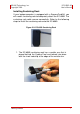
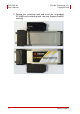
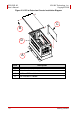
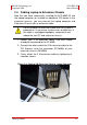


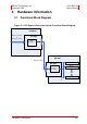
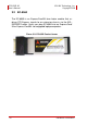
Table Of Contents
- ECS-8582-4S
- Revision History
- Preface
- Table of Contents
- List of Figures
- List of Tables
- 1 Introduction
- 2 Getting Started
- 3 Hardware Information
- 3.1 Functional Block Diagram
- 3.2 EC-8560
- 3.3 PCI-8565 Layout, Connectors and Jumpers
- 3.4 RK-8005 4-Slot Extension Chassis
- 3.5 BP-8005 Layout, Connectors and Jumpers
- Figure 3-7: BP-8005 Backplane Layout
- Table 3-4: BP-8005 Connectors, Jumpers and LED
- Table 3-5: BP-8005 CN1 LED Connector
- Table 3-6: BP-8005 CN2 ATX Power Connector
- Table 3-7: BP-8005 CN3 Fan Connector
- Table 3-8: BP-8005 CN4 ATX Power OK Status Connector
- Table 3-9: BP-8005 JP1 LED Connector
- Table 3-10: BP-8005 JP2 ATX Power Enable Connector
- Table 3-11: BP-8005 JP3 Fan Connector
- 3.6 Extension Cable Options
- 4 Troubleshooting (FAQ)
- Important Safety Instructions
- Warranty Policy
Getting Started 11
ADLINK Technology, Inc. ECS-8582-4S
Copyright 2008 User’s Manual
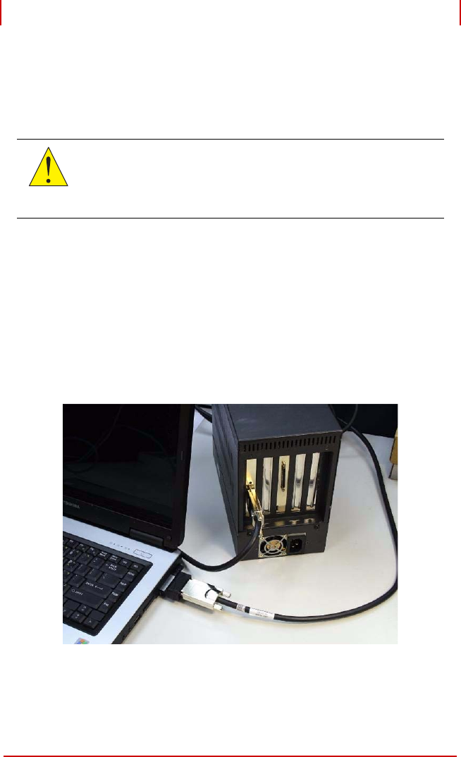
2.4 Cabling Laptop to Extension Chassis
Now that you have successfully installed the ECS-8582-4S into
the laptop computer (or installed an additional PCI device in the
extension chassis), you may connect the laptop computer and
Extension Chassis with an extension cable.
1. Locate your 3 M extension cable. One end should
already be connected to the EC-8560.
2. Connect the other end of the 3 M extension cable to the
PCI Express serial link connector (PCI-8565) of your
extension chassis (RK-8005).
3. Firmly attach the 3 M extension cable by tightening its
retention screws.
Figure 2-4: Cabling 3 M Extension Cable to Laptop Computer
CAUTION:
Do not remove the extension cable after the system is
powered on. It may cause system errors or data loss. If
the cable is unplugged improperly, reconnect it and
reboot the host PC and extension chassis