
User`s manual
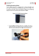
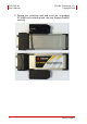
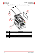
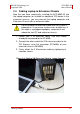


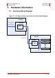

Table Of Contents
- ECS-8582-4S
- Revision History
- Preface
- Table of Contents
- List of Figures
- List of Tables
- 1 Introduction
- 2 Getting Started
- 3 Hardware Information
- 3.1 Functional Block Diagram
- 3.2 EC-8560
- 3.3 PCI-8565 Layout, Connectors and Jumpers
- 3.4 RK-8005 4-Slot Extension Chassis
- 3.5 BP-8005 Layout, Connectors and Jumpers
- Figure 3-7: BP-8005 Backplane Layout
- Table 3-4: BP-8005 Connectors, Jumpers and LED
- Table 3-5: BP-8005 CN1 LED Connector
- Table 3-6: BP-8005 CN2 ATX Power Connector
- Table 3-7: BP-8005 CN3 Fan Connector
- Table 3-8: BP-8005 CN4 ATX Power OK Status Connector
- Table 3-9: BP-8005 JP1 LED Connector
- Table 3-10: BP-8005 JP2 ATX Power Enable Connector
- Table 3-11: BP-8005 JP3 Fan Connector
- 3.6 Extension Cable Options
- 4 Troubleshooting (FAQ)
- Important Safety Instructions
- Warranty Policy

Getting Started 9
ADLINK Technology, Inc. ECS-8582-4S
Copyright 2008 User’s Manual
2.3 Installing PCI Peripheral Cards to an Extension
Chassis
1. Locate your extension chassis, RK-8005 and plug-in the
AC power cord but DO NOT power-on the equipment.
2. Unscrew the four housing screws of the extension chas-
sis using a (cross-head or flat-head) screwdriver. Open
the top cover of the chassis. You should see a row of
four PCI slots along the backplane.
3. Locate your PCI device and remove it from its packag-
ing. (Please wear anti-static gloves and use an anti-
static surface when handling the card).
4. Install your PCI device in an available PCI slot and be
sure to firmly attach it’s bracket to the backplane of the
extension chassis.
5. Close the extension chassis and re-install its housing
screws.
CAUTION:
The following instructions are for illustration purposes
when attempting to install additional PCI devices to your
extension chassis. RK-8005 extension chassis are pre-
installed with one PCI-8565 extension card.