
User`s manual
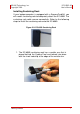
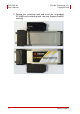
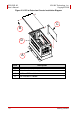
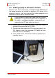
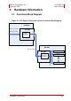
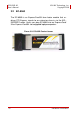
Table Of Contents
- ECS-8582-4S
- Revision History
- Preface
- Table of Contents
- List of Figures
- List of Tables
- 1 Introduction
- 2 Getting Started
- 3 Hardware Information
- 3.1 Functional Block Diagram
- 3.2 EC-8560
- 3.3 PCI-8565 Layout, Connectors and Jumpers
- 3.4 RK-8005 4-Slot Extension Chassis
- 3.5 BP-8005 Layout, Connectors and Jumpers
- Figure 3-7: BP-8005 Backplane Layout
- Table 3-4: BP-8005 Connectors, Jumpers and LED
- Table 3-5: BP-8005 CN1 LED Connector
- Table 3-6: BP-8005 CN2 ATX Power Connector
- Table 3-7: BP-8005 CN3 Fan Connector
- Table 3-8: BP-8005 CN4 ATX Power OK Status Connector
- Table 3-9: BP-8005 JP1 LED Connector
- Table 3-10: BP-8005 JP2 ATX Power Enable Connector
- Table 3-11: BP-8005 JP3 Fan Connector
- 3.6 Extension Cable Options
- 4 Troubleshooting (FAQ)
- Important Safety Instructions
- Warranty Policy
Getting Started 7
ADLINK Technology, Inc. ECS-8582-4S
Copyright 2008 User’s Manual
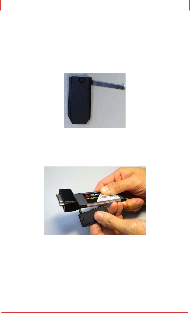
Installing Sustaining Rack
If your laptop computer is equipped with a ExpressCard/54, you
will need a sustaining rack to adequately attach the EC-8560. The
sustaining rack adds secure connectivity. Refer to the following
steps to install the sustaining rack onto the EC-8560.
Figure 2-2: EC-8560 Sustaining Rack
1. The EC-8560 sustaining rack has a metalic arm that is
placed behind the ExpressCard and locked into place
with the short hook/clip at the edge of the metalic arm.