
User`s manual


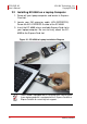
Table Of Contents
- ECS-8582-4S
- Revision History
- Preface
- Table of Contents
- List of Figures
- List of Tables
- 1 Introduction
- 2 Getting Started
- 3 Hardware Information
- 3.1 Functional Block Diagram
- 3.2 EC-8560
- 3.3 PCI-8565 Layout, Connectors and Jumpers
- 3.4 RK-8005 4-Slot Extension Chassis
- 3.5 BP-8005 Layout, Connectors and Jumpers
- Figure 3-7: BP-8005 Backplane Layout
- Table 3-4: BP-8005 Connectors, Jumpers and LED
- Table 3-5: BP-8005 CN1 LED Connector
- Table 3-6: BP-8005 CN2 ATX Power Connector
- Table 3-7: BP-8005 CN3 Fan Connector
- Table 3-8: BP-8005 CN4 ATX Power OK Status Connector
- Table 3-9: BP-8005 JP1 LED Connector
- Table 3-10: BP-8005 JP2 ATX Power Enable Connector
- Table 3-11: BP-8005 JP3 Fan Connector
- 3.6 Extension Cable Options
- 4 Troubleshooting (FAQ)
- Important Safety Instructions
- Warranty Policy

6 Getting Started
ECS-8582-4S ADLINK Technology, Inc.
User’s Manual Copyright 2008
2.2 Installing EC-8560 on a Laptop Computer
1. Power-off your laptop computer and locate its Express-
Card slot.
2. Locate your 3M extension cable (ACL-EXPRESS-3).
Screw the ACL-EXPRESS-3 cable to the EC-8560.
3. Insert the EC-8560 into an available ExpressCard slot in
your laptop computer. Be sure to firmly attach the EC-
8560 to the ExpressCard slot.
Figure 2-1: EC-8560 to Laptop Installation Diagram
NOTE:
NOTE:
The EC-8560 is equipped with a sustaining rack. Please check
if your laptop computer is equipped with an ExpressCard/34 or
ExpressCard/54 for sustaining rack support.