
User`s manual


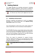
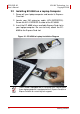
Table Of Contents
- ECS-8582-4S
- Revision History
- Preface
- Table of Contents
- List of Figures
- List of Tables
- 1 Introduction
- 2 Getting Started
- 3 Hardware Information
- 3.1 Functional Block Diagram
- 3.2 EC-8560
- 3.3 PCI-8565 Layout, Connectors and Jumpers
- 3.4 RK-8005 4-Slot Extension Chassis
- 3.5 BP-8005 Layout, Connectors and Jumpers
- Figure 3-7: BP-8005 Backplane Layout
- Table 3-4: BP-8005 Connectors, Jumpers and LED
- Table 3-5: BP-8005 CN1 LED Connector
- Table 3-6: BP-8005 CN2 ATX Power Connector
- Table 3-7: BP-8005 CN3 Fan Connector
- Table 3-8: BP-8005 CN4 ATX Power OK Status Connector
- Table 3-9: BP-8005 JP1 LED Connector
- Table 3-10: BP-8005 JP2 ATX Power Enable Connector
- Table 3-11: BP-8005 JP3 Fan Connector
- 3.6 Extension Cable Options
- 4 Troubleshooting (FAQ)
- Important Safety Instructions
- Warranty Policy

xi
ADLINK Technology, Inc. ECS-8582-4S
Copyright 2008 User’s Manual
List of Figures
Figure 2-1: EC-8560 to Laptop Installation Diagram.......................... 6
Figure 2-2: EC-8560 Sustaining Rack................................................ 7
Figure 2-3: PCI to Extension Chassis Installation Diagram ............. 10
Figure 2-4: Cabling 3 M Extension Cable to Laptop Computer........ 11
Figure 3-1: PCI Express Extension System
Functional Block Diagram.............................................. 15
Figure 3-2: EC-8560 Product Image ................................................ 16
Figure 3-3: PCI-8565 Mechanical Layout......................................... 17
Figure 3-4: RK-8005 Chassis Front and Back View......................... 19
Figure 3-5: RK-8005 Chassis Top View........................................... 20
Figure 3-6: RK-8005 Side View........................................................ 20
Figure 3-7: BP-8005 Backplane Layout ........................................... 21
Figure 3-8: Standard 3 M extension cable (ALC-PCEEXT-3).......... 25