
User`s manual


Introduction 11
MXC-6300
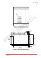
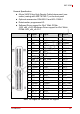
Table 1-1: Front Panel I/O Connector Legend
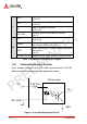
1.5.1 Power Button
The power button is a non-latched push button with a blue LED
indicator. System is turned on when the button is depressed, and
the power LED lights. If the system hangs, depress the button for
5 seconds to turn off the system completely.
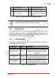
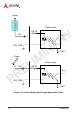
1.5.2 LED Indicators
In addition to the LED of the power button, three LEDs on the front
panel indicate the following.
Table 1-2: LED Indicators
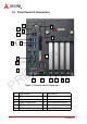
G Gigabit Ethernet P PCI express x8 Slot
H CFast (Push-Push, Type II) Q PCI express x16 Slot
I DVI-I connector R
Reserved space for dual-
slot width PCIex16 graphic
card
NOTE:
NOTE:
1 PCE x16 + 1 PCI expansion slot, with PCIe x16 signal con-
verts to PCIe x8 if two PCI x8 cards are installed
LED indicator Color Description
Watchdog (WD) Yellow
Indicates watchdog timer status. When
watchdog timer starts, the LED flashes.
When the timer is expired, the LED
remains lit..
Hard disk drive
(HD)
Orange
Indicates the HDD operating state.
When the SATA hard drive or CF card is
active, the LED indicator flashes.
CompactFlash
card (CF)
Green
Indicates the operating state of the CF
card on the front panel. The LED
indicator flashes when CF card is active.
PRELIMINARY