
User`s manual
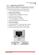
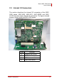

24 System Description
Matrix MXC-2000 Series
User’s Manual
2.3.1 CompactFlash Socket
The internal CompactFlash socket is connected to chipset via IDE
interface, and can be used as an alternative storage device for
system installation. You can boot up the MXC-2002/2011/2002D/
2011D controller via a CF card with OS installed. Due to the nature
of IDE interface, the CF card is not hot-pluggable and must be
installed before system power on. Please refer to section 3.4 for
the illustration of installing a CF card.
2.3.2 COM Ports Setting Jumpers
These six jumpers (JP2/JP3/JP4/JP5/JP6/JP7) are used for con-
figuring COM1 and COM2 ports to RS-232/422/485 mode. Please
refer to section 3.3 for the illustration of setting COM1 and COM2
ports.
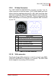
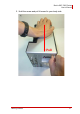
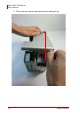
2.3.3 SATA Connector
The MXC-2002/2011/2002D/2011D controller provides a SATA
Gen.1 port. The SATA host controller supports two modes of oper-
ation, the legacy mode using I/O space and AHCI mode using
memory space. This SATA connector is designed for installing a
2.5” hard disk drive or solid state disk (SSD). The HDD or SSD
must be installed into SATA connector with a specific bracket
mounted on the chassis. Please refer to section 3.1 for the illustra-
tion of installing a 2.5” hard disk drive or SSD.
2.3.4 Clear CMOS Button
When encountering the abnormal condition that causes the MXC-
2002/2011/2002D/2011D controller failed to boot, you can try to
clear the BIOS content stored in CMOS and restore to the default
setting. To clear CMOS, just press the button and hold on for 1~2
second then release it. After doing that, the CMOS will restore to
the factory default setting.