
User`s manual


Reference Manual 127
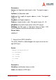
DataLen: [In] Length of data, in bits. The typical range is 0 - 16.
RegData: [In] Value to be written to the SPI register.
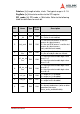
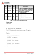
SPI_mode: [In] SPI mode, a 16-bit data. Refer to the following
table for definitions for each bit.
Bit Name Type
Default
Value
Description
15:11 Reserved
10
three_wire
_en
RW 1’b0
1 = 3-wire is enabled;
0 = 3-wire is not enabled;
9 bst_end RW 1’b0
1 = the next R/W access is the last
access of a burst access;
0 = the next R/W access is not the last
access of a burst access
(only valid for burst mode)
8
sdo_separ
ate
RW 1’b0
1 = pin sdi and pin sdo are separated;
0 = pin sdi and pin sdo are shared;
7
cs1_en_va
lue
RW 1’b0
1 = the chip-select enable logic value
for cs1 is 1
0 = the chip-select enable logic value
for cs1 is 0
6
cs0_en_va
lue
RW 1’b0
1 = the chip-select enable logic value
for cs0 is 1
0 = the chip-select enable logic value
for cs0 is 0
5 cs1_en RW 1’b0
1 = output cs1 is enabled;
0 = output cs1 is disabled;
4 cs0_en RW 1’b1
1 = output cs0 is enabled;
0 = output cs0 is disabled;
3 read RW 1’b0
1 = do read access;
0 = do non-read access (write or other
operation like erase,
erase_write_enable/disable);