PCI-MPG24 4-CH MPEG4 Hardware Video Compression Card User’s Manual Manual Rev. 2.03 Revision Date: January 23, 2008 Part No: 50-15035-1030 Advance Technologies; Automate the World.
Copyright 2008 ADLINK TECHNOLOGY INC. All Rights Reserved. The information in this document is subject to change without prior notice in order to improve reliability, design, and function and does not represent a commitment on the part of the manufacturer. In no event will the manufacturer be liable for direct, indirect, special, incidental, or consequential damages arising out of the use or inability to use the product or documentation, even if advised of the possibility of such damages.
Getting Service from ADLINK Customer Satisfaction is top priority for ADLINK Technology Inc. Please contact us should you require any service or assistance. ADLINK TECHNOLOGY INC. Web Site: http://www.adlinktech.com Sales & Service: Service@adlinktech.com TEL: +886-2-82265877 FAX: +886-2-82265717 Address: 9F, No. 166, Jian Yi Road, Chungho City, Taipei, 235 Taiwan Please email or FAX this completed service form for prompt and satisfactory service.
Table of Contents 1 Introduction ........................................................................ 1 1.1 1.2 1.3 1.4 1.5 Features............................................................................... 1 Real-time MPEG4 Hardware Video Encoding ................ 1 Adjustable Video Quality ................................................. 2 Real-time Raw Data Preview .......................................... 2 Video Decoding ..............................................................
Tools ............................................................................. 44 Appendix A: Glossary ........................................................ 47 Brightness: .................................................................... 47 CCIR: ............................................................................ 47 Composite Video: ......................................................... 47 CIF: ............................................................................... 47 EIA: ...
List of Tables Table Table Table Table Table Table Table Table Table Table Table Table Table Table Table 1-1: 1-2: 1-3: 1-4: 1-5: 1-6: 1-7: 1-8: 1-9: 2-1: 2-2: 2-3: 2-4: 2-5: 2-6: List of Tables Number of Frames .................................................... 1 Configuration 1 – NTSC, CIF (320 x 240) ................ 7 Configuration 2 – NTSC, Full D1 (720 x 480) ........... 8 Configuration 3 – PAL, CIF (352 x 288) ................... 9 Configuration 4 – PAL, Full D1 (720 x 576) ............
List of Figures Figure 1-1: Figure 1-2: Figure 1-3: Figure 2-1: Figure 2-2: Figure 2-3: Figure 2-4: Figure 2-5: Figure 4-1: iv Real-time Raw Data Preview - single channel........... 2 Real-time Raw Data Preview - four channels ............ 3 AVI video file format................................................... 4 PCI-MPG24 ............................................................. 19 Watchdog reset cable .............................................. 19 BNG Interface cable ...........................
1 Introduction The PCI-MPG24 is a MPEG4 hardware video compression card that provides four channels of real-time full D1 size MEGP4 video encoding and decoding with a preview function for digital video surveillance applications. This 32-bit, 33MHz PCI bus frame grabber simultaneously captures and encodes four video analog streams in real time. It accepts standard composite color (PAL, NTSC) or monochrome video formats (CCIR, EIA) cameras inputs. Each PCI-MPG24 card has a unique hardware ID number.
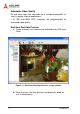
Adjustable Video Quality Bit and frame rates are adjustable to fit variable bandwidths, as seen in remote Internet applications. I, IP, IBP, and IBBP GOP structures are programmable for enhanced video quality. Real-time Raw Data Preview X Single channel: real-time preview and display by VGA resolution. Figure 1-1: Real-time Raw Data Preview - single channel X 2 Four channels: real-time preview and display by quad format simultaneously.
Figure 1-2: Real-time Raw Data Preview - four channels Video Decoding Smart software video decoding for playback or remote client monitoring and NO need to plug-in PCI-MPG24 card. Save File The video can be saved to AVI video file format. Users can playback AVI file by Microsoft Media Player.
Figure 1-3: AVI video file format I/O Lines The PCI-MPG24 is fitted with TTL compatible I/O lines protected against overloads and electrostatic discharges. Each line may be configured as an input or output. They can be used to trigger acquisition or report alarm signals. Watchdog Timer A hardware watchdog is available on the PCI-MPG24 that is able to monitor PC application operation and will automatically reset the PC after a programmable inactivity time-out.
Supported software X Support Microsoft DirectX X Support Visual Studio .net, VC++, and C++ Builder programming language X Support Windows 2000 and Windows XP. X Sample programs X ‘ViewCreator for DirectX’ utility for assistance in the initial test and functional evaluation. 1.
requests of more than two channels, full D1 size real-time decode to specifications below: Z Pentium 4, 2.4GHz CPU, 256MB DDR RAM above. X Please refer to 1.4 PCI-MPG24 Benchmark for performance limitations. X One PCI-MPG24 consumes an extra 150MB RAM memory for preview and recording. 1.
Configuration 1 – NTSC, CIF (320 x 240), 30 sec.
Configuration 2 – NTSC, Full D1 (720 x 480), 30 sec.
Configuration 3 – PAL, CIF (352 x 288), 30 sec.
Configuration 4 – PAL, Full D1 (720 x 576), 30 sec.
Configuration 1 – NTSC, CIF (320 x 240), 30 sec.
Configuration 2 – NTSC, Full D1 (720 x 480), 30 sec.
Configuration 3 – PAL, CIF (352 x 288), 30 sec.
Configuration 4 – PAL, Full D1 (720 x 576), 30 sec.
1.5 Suggests for Optimizing File I/O 1. Format each physical hard disk drive with only one partition. 2. Format the disk drive with NTFS (Windows only). 3. Format the disk driver with a larger cluster size (at least 64 KB in size). 4. Regularly defragment the partition. 5. Do not use NTFS compression on the partition (only for Windows only). 6. If you have a separate hard disk for data files, use a separate IDE controller.
16 Introduction
2 Hardware Reference 2.1 PCI-MPG24 Specification Video Input X Four composite video color digitizers. X Video input interface: DB15 pin female connector X Support PAL/NTSC/CCIR/EIA standard cameras.
Watch Dog Timer X For monitoring the PC’s application operation and will reset the PC after a programmable inactivity time-out. X Interface: 2-pin header User EEPROM X Support 1K bit EEPROM for user defined purposes Form Factor X 32bit/ 33MHz PCI bus half size board. Power Consumption 18 X 3.3V @ 2.8A max X 5V @ 0.8A max X +12V @ 0.1A max X -12V @ 0.
PCI-MPG24 Appearance Figure 2-1: PCI-MPG24 PCI-MPG24 Standard accessories Figure 2-2: Watchdog reset cable Hardware Reference 19
Figure 2-3: BNG Interface cable Figure 2-4: All in One CD 20 Hardware Reference
PCI-MPG24 Interface Figure 2-5: Outline Drawing Connectors & Pin Definitions Video Inputs: CN3 Pin Type Function Pin Type Function 1 IN Video Port 0 9 -- GND 2 IN Video Port 1 10 -- GND 3 IN Video Port 2 11 -- GND 4 IN Video Port 3 12 -- GND 5 -- -- 13 -- GND 6 -- -- 14 -- -- 7 -- -- 15 -- -- 8 -- -- Table 2-2: Video Inputs - CN3 Hardware Reference 21
GPIO: CN2 Pin Type Function 1 IN GPIO IN 1 2 IN GPIO IN 2 3 IN GPIO IN 3 4 IN GPIO IN 4 5 G GND 6 OUT GPIO OUT 1 7 OUT GPIO OUT 2 8 OUT GPIO OUT 3 9 OUT GPIO OUT 4 10 G GND 11 G GND 12 G GND 13 G GND 14 G GND 15 P +5V power output Table 2-3: GPIO - CN2 Watchdog Timer Reset 2 JP 1 Pin Function 1 System reset 2 GND Table 2-4: Watchdog Timer Reset 22 Hardware Reference
DIP switch & Setting S1: Card ID setting & NTSC/PAL mode setting S1 Pin Function ON OFF (Default) 1 Card ID BIT 0 1 0 2 Card ID BIT 1 1 0 3 Card ID BIT 2 1 0 4 NTSC / PAL PAL NTSC Table 2-5: S1 Card ID setting & NTSC/PAL mode setting Maximum support for 8 PCI-MPG24 cards in a single system Card ID S1 Pin3 S1 Pin2 S1 Pin1 0 OFF OFF OFF 1 OFF OFF ON 2 OFF ON OFF 3 OFF ON ON 4 ON OFF OFF 5 ON OFF ON 6 ON ON OFF 7 ON ON ON Table 2-6: Pin setting for 8 PCI
24 Hardware Reference
3 Installation Guide 3.1 Software Driver Installation Windows Driver Installation 1. Operating Systems Supported Z Windows 2000 Professional with SP4 Z Windows XP Professional with SP2 Z Windows Vista 2. Other necessary software packages Z Microsoft DirectX 9.
To install the driver: 1. Insert PCI-MPG24 cards to your system. Power the computer on. 2. Cancel Found New Hardware wizards. 3. Double click SETUP.exe in the PCI-MPG24 setup disk. The driver will begin installing.
4. Click Next.
5. Click Next, or click Change to install in a different folder.
6. Click Install to begin installation.
30 Installation Guide
7. Click Finish.
8. Go to system control panel and select multimedia devices.
Linux Driver Installation Prepare Operating System - Install RedHat 9 This section describes how to install RadHat 9 if your system does not have Linux operation system on the computer. 1. Partition a free section about 10G size from hard disk before install RH9. 2. Insert the RH9 CD into your CD driver and reboot with CD supported. 3. System will install automatically after computer reboots. 4. Follow Linux installation step by step.
6. Upgrade the gcc compiler to version 3.4 if you have an old one. Enter the following command to check the version of gcc: # gcc --version Configure the kernel. 1. Start the kernel configuration program. # cd /usr/src/linux # make menuconfig 2. Make sure the following items to be chosen when configuring the kernel.
Build the kernel. 1. Build the kernel to generate a new image file bzImage. # make bzImage 2. Build the configured loadable modules in order to load them when needed. # make modules # make modules_install Run the kernel 1. Copy the new image file and the System.map to /boot directory. # cp /usr/src/linux/arch/i386/boot/bzImage /boot/ vmlinuz-2.6.9 # cp /usr/src/linux/System.map /boot/System.map2.6.9 # cd /boot # rm -f System.map # ln -s System.map-2.6.9 System.map # mkinitrd /boot/initrd-2.6.9.img 2.6.
#cd devfsd #make & make install 5. Make USB mouse/keyboard work: If you are using USB mouse for Kernel 2.6.9, please modify / etc/rc.sysinit, replace "mousedev" with "usbmouse". If you are using USB keyboard for Kernel 2.6.9, please modify /etc/ rc.sysinit, replace "keybdev" with "usbkbd". 6. Reboot the Linux operation system # reboot Install the Driver Install driver under Linux terminal following these steps: 1. Uncompress MPG24 package: # cd /home # tar zxvf MPG24-kernel2.6.9.tar.gz 2.
SupportFiles/*.bin and SupportFiles/fix_setting.txt to /lib/firmware before doing step 4 of Install Driver. Sample Programs The sample programs are located on "Src/App" folder 1. Encode: #./go-server A 4 channels full D1 MPEG4 sample.This sample program initialize MPG24, and compress the video into MPEG4 avi files, Video_0.avi, Video_1.avi, Video_2.avi, Video_3.avi. 2. Preview: #./v4lsample This is a live preview sample program. The program is based on Video4Linux 2 API.
If something does not work as expected, try the following to see the available options: # ./configure --help The configure script prints a summary of enabled and disabled options. If you have something installed that configure fails to detect, check the file configure.log for errors and reasons for the failure. Repeat this step until you are satisfied with the enabled feature set. 2.
5. Once aligned with an empty slot, press the board firmly but carefully into the connector. 6. Anchor the board by replacing the screw. 7. Connect your video sources for image acquisition tests. For details, refer to the ‘ViewCreator” utility.
40 Installation Guide
4 ViewCreator Utility Once hardware installation is complete, ensure that they are configured correctly before running the ViewCreator utility. This chapter outlines how to establish a vision system and how to manually control PCI_MPG24 cards to verify correct operation. ViewCreator provides a simple yet powerful means to setup, configure, test, and debug the vision system.
4.2 Component Description Figure 4-1: Component Description Tree Browser The Tree Browser window lists the PCI-MPG24 cards and video ports available at the local computer. Image View The Image View window displays Full, CIF, and QCIF size images and image effects. Playback is displayed in an individual window. Toolbar The toolbar simplify user’s operation. Full functions can be found on the menu.
4.3 Operation Theory ViewCreator provides many functions for the PCI-MPG24 card as described below: Preview Single channel display Click on the video Port icon in the Tree Browser window. A video frame will appear in the Image View window. 2x2 channels (Quad mode) Click on the card icon in the Tree Browser window. All video ports in that card will appear in the Image View window. You also can click Single/Quad Image on the toolbar to toggle between single channel display and 2x2 channels display.
stream to a file. The path of the file can be set in the Set Recording command of menu Record. Configurations Record Execute the Record Filter command of menu Configuration to open a setting menu. Click OK or Apply to apply these settings. This command can only be used in the single channel display mode (select a video Port icon in the Tree Browser window). Preview Execute the Preview Filter command of menu Configuration to open a setting menu.
EEPROM Execute EEPROM command in the menu Tools to bring up the EEPROM dialog box. Enter the offset and output values, and then click the Write button to write the value into the EEPROM. Enter the offset value and click the Read button to read the value from the EEPROM. Valid offset values are between 0-127. Valid output values are in the range of 0 and 255. The value in the EEPROM will not be erased when the system is powered off.
46 ViewCreator Utility
Appendix Appendix A: Glossary Brightness: Attribute of a visual sensation according to which an area appears to exhibit more or less light CCIR: Committee Consulat International Radiotelegraphique. This is a standards committee of the International Telecommunications Union, which made the technical recommendation for European 625 line standard for video signals.
Frame: One frame (two fields) of video contains the full vertical interlaced information content of the picture. For NTSC this consists of 525 lines and PAL a frame is consisted of 625 lines. Gamma: Cathode ray tubes (CRTs) do not have a linear relationship between brightness and the input voltage applied. To compensate for this non-linearity, a pre distortion or gamma correction is applied, generally at the camera source. A value of gamma equal to 2.2 is typical, but can vary for different CRT phosphors.
Ireland) and PAL M (hybrid standard, having the same resolution as NTSC, but uses PAL transmission and color coding technology). Saturation: A characteristic describing color amplitude or intensity. A color of a given hue may consist of low or high saturation value, which relates to the vividness of color. AGC Abbreviation for automatic gain control. On a TV or VCR, AGC is a circuit that automatically adjusts the incoming signal to the proper levels for display or recording.
Appendix B: Standard Compliance Notice for USA Compliance Information Statement (Declaration of Conformity Procedure) DoC FCC Part 15 This equipment has been tested and found to comply with the limits for a Class A digital device, pursuant to Part 15 of the FCC Rules. These limits are designed to provide reasonable protection against harmful interference in a residential installation or when the equipment is operated in a commercial environment.
Notice for Europe This product is in conformity with the Council Directive 89/336/EEC amended by 92/31/EEC and 93/ 68/EEC This equipment has been tested and found to comply with EN55022/CISPR22 and EN55024/CISPR24. To meet EC requirements, shielded cables must be used to connect a peripheral to the card. This product has been tested in a typical class B compliant host system. It is assumed that this product will also achieve compliance in any class A compliant unit.
52 Appendix
Warranty Policy Thank you for choosing ADLINK. To understand your rights and enjoy all the after-sales services we offer, please read the following carefully. 1. Before using ADLINK’s products please read the user manual and follow the instructions exactly. When sending in damaged products for repair, please attach an RMA application form which can be downloaded from: http:// rma.adlinktech.com/policy/. 2.
3. Our repair service is not covered by ADLINK's guarantee in the following situations: X Damage caused by not following instructions in the User's Manual. X Damage caused by carelessness on the user's part during product transportation. X Damage caused by fire, earthquakes, floods, lightening, pollution, other acts of God, and/or incorrect usage of voltage transformers. X Damage caused by unsuitable storage environments (i.e. high temperatures, high humidity, or volatile chemicals).