
User`s manual


Table Of Contents
- NuPRO-935A
- Revision History
- Preface
- Table of Contents
- List of Figures
- List of Tables
- 1 Introduction
- 2 Hardware Information
- 2.1 Rear Panel I/O Ports
- 2.2 Board Layout
- 2.3 Onboard Connectors
- ATX 12V Power Connector (CN7)
- CPU Fan Connector (FAN2)
- System Fan Connector (FAN1)
- IDE Connector (CN10)
- Floppy disk drive connector (CN8)
- Parallel Port (CN13)
- HD Audio Daughter Board Connector (CN4)
- COM1 Connector (RS-422/485/485+) (CN6)
- COM1/COM2 Connector (RS-232) (CN5/6)
- USB 2.0 Connector (CN11-12)
- External Keyboard/Mouse Connector (CN19)
- Serial ATA Connectors (CN2-3)
- System Panel Connector (CN1)
- 2.4 Jumpers
- 3 Getting Started
- 4 Driver Installation
- 5 BIOS Setup
- Appendix A - Watchdog Timer
- Appendix B System Resources
- Important Safety Instructions
- Getting Service
Hardware Information 19
NuPRO-935A
2.3 Onboard Connectors
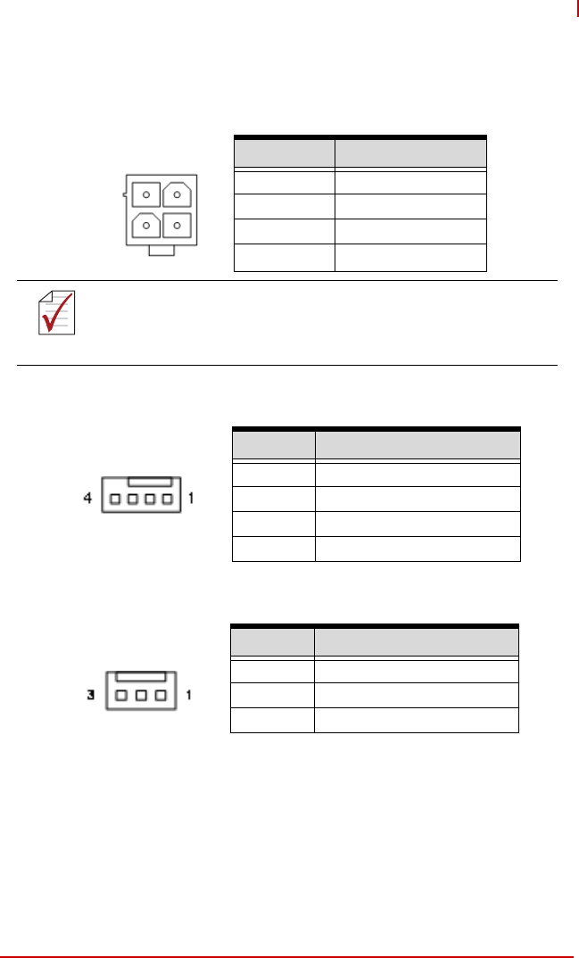
ATX 12V Power Connector (CN7)
CPU Fan Connector (FAN2)
System Fan Connector (FAN1)
Pin # Signal
1GND
2GND
3+12V DC
4
+12V DC
NOTE:
NOTE:
The ATX 12V power connector must be connected to provide
sufficient power to the SBC in either ATX or AT modes . See
“Installing the Power Connectors” on page 34.
Pin # Signal
1GND
2 Fan power (+12V)
3 Fan Tachometer
4
Fan Speed Control
Pin # Signal
1GND
2 Fan power (+12V)
3 Fan Tachometer
1
3
2
4