
User`s guide


48
Operation Theory
4.4 General Purpose Timer/Counter Operation
Two independent 16-bit up/down timers/counters are designed within
FPGA for various applications. They have the following features:
Count up/down controlled by hardware or software
Programmable counter clock source (internal or external clock up to
10MHz)
Programmable gate selection (hardware or software control)
Programmable input and output signal polarities (high active or low
active)
Initial Count can be loaded from software
Current count value can be read-back by software without affecting
circuit operation
4.4.1 Timer/Counter functions basics
Each timer/counter has three inputs that can be controlled via hardware or
software: clock input (GPTC_CLK), gate input (GPTC_GATE), and
up/down control input (GPTC_UPDOWN). The GPTC_CLK input provides
a clock source input to the timer/counter. Active edges on the GPTC_CLK
input make the counter increment or decrement. The GPTC_UPDOWN
input controls whether the counter counts up or down. The GPTC_GATE
input is a control signal which acts as a counter enable or a counter trigger
signal under different applications.
The output of timer/counter is GPTC_OUT. After power-up, GPTC_OUT is
pulled high by a pull-up resister about 10kΩ. Then GPTC_OUT goes low
after the DAQ-2213/2214 initialization.
All the polarities of input/output signals can be programmed by software. In
this chapter, for easier explanation, GPTC_CLK, GPTC_GATE, and
GPTC_OUT are assumed to be active high or rising-edge triggered in the
figures.
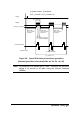
4.4.2 General Purpose Timer/Counter modes
Eight programmable timer/counter modes are provided. All modes start
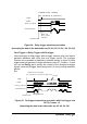
operating following a software-start signal that is set by the software. The
GPTC software reset initializes the status of the counter and re-loads the
initial value to the counter. The operation remains halted until the soft-
ware-start is re-executed. The operating theories under different modes
are described as below.