
User`s guide


Operation Theory • 25
4.1.1 DAQ/PXI-2204 AI Data Format
4.1.1.1 Synchronous Digital Inputs (for DAQ/PXI-2204 only)
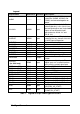
When each AD conversion is completed, the 12-bit converted digital data
accompanied with 4 bits of SDI<3..0> from CN2 will be latched into the
16-bit register and data FIFO, as shown in Fig 9 and Fig 10. Therefore,
users can simultaneously sample one analog signal with four digital signals.
The data format of every acquired 16-bit data is of the form:
D11, D10, D9 ....... D1, D0, b3, b2, b1, b0
Where
D11, D10, D9 ....... D1, D0: 2’s complement A/D 12-bit data
b3, b2, b1, b0: Synchronous Digital Inputs SDI<3..0>
ADC
AD<11..0>
16-bit
Register
SDI<3..0>
from CN2
From
Instrumentation
Amplifier
4
12
16
AD
Data
FIFO
Ain
SDI<3..0>
CLK
nADBUSY
nADCONV
AD_conversion
nADBUSY
Figure 9: Synchronous Digital Inputs Block Diagram
AD_conversion
nADBUSY
16 bits data(including AD<11..0> and SDI<3..0>
latched into AD Data FIFO
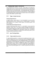
Figure 10: Synchronous Digital Inputs timing
Note: The analog signal is sampled when an AD conversion starts (falling
edge of signal AD_conversion), while SDI<3..0> are sampled right
after an AD conversion is completed (rising edge of signal nAD-
BUSY). Precisely SDI<3..0> are sampled with 280ns lag to the
analog signal.