
User`s guide


20 • Signal Connections
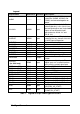
Legend:
Signal Name Reference
Direction
Description
AIGND -------- --------
Analog ground for AI. All three ground
references (AIGND, AOGND, and
DGND) are connected together on
board
AI<0..63> AIGND Input
Analog Input Channels 0~63. Each
channel pair,AI<i, i+32> (I=0..31) can
be configured either two single-ended
inputs or one differential input
pair(marked as AIH<0..31> and
AIL<0..31>)
AISENSE AIGND Input
Analog Input Sense. This pin is the
reference for any channels AI<0..63>
in NRSE input configuration
EXTATRIG AIGND Input External AI analog trigger
DA0OUT AOGND Output AO channel 0
DA1OUT AOGND Output AO channel 1
AOEXTREF AOGND Input External reference for AO channels
AOGND -------- -------- Analog ground for AO
EXTWFTRIG DGND Input External AO waveform trigger
EXTDTRIG DGND Input External AI digital trigger
RESERVED -------- Output
Reserved for future use. Please leave
it open
SDI<0..3>
(for 2204 only)
DGND Input
Synchronous digital inputs. These 4
digital inputs are sampled simultane-
ously with the analog signal input
GPTC<0,1>_SRC DGND Input Source of GPTC<0,1>
GPTC<0,1>_GATE DGND Input Gate of GPTC<0,1>
GPTC<0,1>_OUT DGND Input Output of GPTC<0,1>
GPTC<0,1>_UPDOWN DGND Input Up/Down of GPTC<0,1>
EXTTIMEBASE DGND Input External Timebase
DGND -------- -------- Digital ground
PB<7,0> DGND PIO* Programmable DIO of 8255 Port B
PC<7,0> DGND PIO* Programmable DIO of 8255 Port C
PA<7,0> DGND PIO* Programmable DIO of 8255 Port A
AFI0 DGND Input
Auxiliary Function Input 0
(ADCONV, AD_START)
AFI1 DGND Input
Auxiliary Function Input 1
(DAWR, DA_START)
Table 7: Legend of 68-pin VHDCI-type connectors