
Specifications


1-4 Introduction
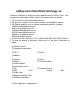
Pin Definitions of ND-6011/D
Pin # Signal Name Description
1
IN+ Analog Input Positive Terminal
2 IN- Analog Input Negative Terminal
3 DO 1/ HI Digital Output Channel 1
or High alarm status output
4 DI 0 / EV Digital Input Channel 0
or event counter input
5 DO 0 / LO Digital Output Channel 0
or Low alarm output
6 DEFAULT* Initial state setting
7 (Y) DATA+ RS-485 series signal, positive
8 (G) DATA- RS-485 series signal, negative
9 (R) +Vs Power supply, +10V~+30V
10 (B) GND Ground
11 TC(+) Thermocouple Input positive Terminal
12 TC(-) Thermocouple Input negative Terminal
Functional Block Diagram of ND-6011/D
GND
+ 5V
Power Input
+10V ~ +30V
Power
Regulator & Filter
Data +
Data -
RS-485
Rec/Drv
Micro
Processor
EEPROM
Config Data
Safe Value
Watchdog/Power Failure
Supervisor
ADC
1-bit
Digital Input
1-bit
Digital Input
2-bits
Digital Output
Analog
Signal
DO0
DO1
DI0
Default*
Pin
CJC
LED Display
(only ND-6011/D)