
User`s guide


APDCAM User’s Guide
Page 9/32
the detector surface which can be set up via software to emit various levels of constant
light on the detector, thus allowing calibration. The light level is not strictly proportional
to the setting and the illumination of the detector is not uniform, therefore the calibration
light cannot be used for calibrating the relative sensitivity of the pixels.
The calibration light is also useful for setting up the optical system. As APDCAM has
low spatial resolution viewing its image does not help in adjusting the lens focus. Instead
it can be done by illuminating the detector with the calibration light and observing its
image on a screen at the object.
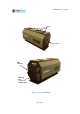
2.8. The detector and its operation
The detector has 32 identical Avalanche Photodiode elements (pixels) biased from a
single voltage. The bias voltage determines the internal gain of the detector. The detector
bias voltage should be set between 200-400V using the appropriate control register. Al-
though the detector and electronics are protected from overload, damage cannot be ex-
cluded if e.g. only a single pixel is illuminated over an extensive period of time. To pro-
tect accidental switch-on of the bias voltage a voltage enable register is provided where
an appropriate code should be entered. Voltage can be switched on only after this.
An additional protection against overload is provided by the digital electronics. If en-
abled it can switch off the detector bias voltage when the signal level is above a certain
limit over a predefined time.
In order to stabilise the gain the detector temperature should be kept constant. This is
accomplished by a temperature control circuit. The standard detector temperature is 18 C
which under normal room temperature does not require too much cooling and prevents
condensation of humidity. If the environmental temperature is much lower or higher 20-
25 Celsius the detector reference temperature can be set to a different value.
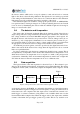
2.9. Data acquisition
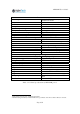
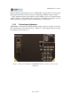
The logical scheme of the data acquisition is shown in Figure 2. This scheme is oper-
ating for all 32 channels independently; all channels can be enabled/disabled. The Analog
to Digital Converter (ADC) continuously samples the amplified detector signal to 14 bits
at a frequency between 10-50 MHz. A configurable digital filter provides high frequency
cutoff. The filtered signal is resampled at a lower frequency or using an external clock to
reduce data load to the computer. The data output can be controlled from external or in-
ternal trigger or software command. A ring buffer is also available which can store the
last maximum 1023 resampled data. When the trigger arrives data output starts with the
contents of the buffer, this post-trigger operation is possible. This is very useful in com-
ADC
Digital filter
Resampling
Output control
Trigger
Fi
g
ure 2. Lo
g
ical scheme o
f
the basic data ac
q
uistion s
y
tem.