
User`s guide


APDCAM User’s Guide
Page 7/32
2. Using APDCAM
2.1. Power connection
APDCAM is delivered with an external 12 V DC power adaptor. This unit has a re-
placeable power cord, please use one which matches your local mains outlet. The camera
needs a single 12 V DC input, maximum current is 6A. The power adaptor is usable from
100 to 230 V mains voltage.
2.2. Operating environment
Some effort might be needed in the setup to minimise noise pick up by the camera. Al-
though APDCAM is housed in a grounded Aluminium enclosure and the detector and
analog amplifiers are housed in an additional Faraday shield strong environmental elec-
trical noise sources might cause disturbances in the signals. To avoid such conditions
separate the camera ground from noise electronic equipment. The camera housing is con-
nected to electrical ground on the power supply mains connector.
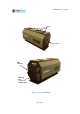
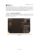
2.3. Camera cooling
APDCAM has three independent fans on the top of the device which circulate air from
the openings on the lower part of the camera out through the fans. The openings should
be free to provide the necessary air flow. In the default setup the speed of the three fans is
controlled automatically, their speed will depend on the temperature of the internal com-
ponents. If this is not desirable the fans can also be set to fixed speed.
2.4. Configuration
The operating parameters of APDCAM are set up in two internal register tables, one for
the data acquisition and one for the camera control. Status of the camera can also be read
from these registers. Settings are stored in non-volatile memory, therefore after switching
off and on the camera the setup will remain the same. There are a few exceptions from
this rule:
Detector bias voltage is always off and disabled after switching on the camera.
The desired number of samples in the measurement are set to 0 on power-on.
The camera also contains configuration information which can only be read by the user.
An example is the maximum allowed detector bias voltage. These register values can be
changed by the manufacturer only.
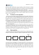
2.5. PC communication
APDCAM can be connected to a PC either via UTP cable or fibre optics communica-
tions. In both cases Gigabit Ethernet is used with 100/10 Mbit as fallback. For using the
maximum data acquisition bandwidth it is essential to use a Gigabit interface card on the
PC side which connects to the internal bus via a PCI Express interface. A card connected
to the PCI bus will not deliver the maximum performance although camera operation at
lower acquisition speeds will not be affected.
If UTP (electrical) connection is intended simply connect a Gbit compatible UTP ca-
ble between the APDCAM
UTP port and the PC interface card. In case of optical com-