
User`s guide


APDCAM User’s Guide
Page 20/32
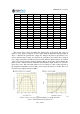
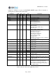
Figure 9. shows the simulated frequency transfer functions of the same cases. From
these it is clear that the FIR filter is effective down to about 1/10-th of the ADC fre-
quency. For lower frequency cutoffs it can be used in combination with the recursive
filter. The recursive filter works at least down to 100 kHz, but at these low frequency cuts
the FIR filter has no effect.
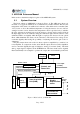
After the filter the desired number of output bit resolution (8,12 or 14 bits, see RESO-
LUTION register) is selected by keeping the most significant bits.
The resulting amount of data could not be transferred through the Ethernet connection
when all the channels are operating, therefore some data reduction is needed. This can be
done either by reducing the number of active channels or by resampling the data (decima-
tion) to lower frequency.
Channels can be enabled individually, see CH_ENABLE register.
Resampling can be done for all active channels in the same way. The resampling clock
can be either a divided version of the ADC clock (see register
SAMPLEDIV_X_7) or it can
be an external input clock. In this latter case it has to be noted, that the data acquisition
unit will not sample exactly at the time of the input clock pulse, but will take the latest
sample when the sample clock arrives. Depending on ADC clock This can result in
20...100 ns jitter.
Figure 9. Simulated frequency transfer functions of the filter cases listed inTable 7. Filter
coefficients for some selected cases.Table 7 .