
User`s guide


APDCAM User’s Guide
Page 19/32
If the recursive filter is not to be used, COEFF_06=0. The impulse transfer function h
i
of the FIR filter should be calculated at 5 points using 1/f
ADC
as the time resolution of the
function. This can be done with some filter design toolbox. If the FIR filter is not to be
used h
1
is 1, all the others are 0. These h
i
coefficients should be normalised by their sums
and multiplied by (4096-c)/8 to yield the coefficients of the FIR filter:
COEFF_0i =
5
1i
i
i
h
h
(4096-COEFF_06)/8, i=1...5.
The two last coefficients should always have the same value:
COEFF_07 = 0, COEFF_08=9.
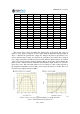
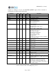
The filter coefficients are listed for selected cases in Table 7. Here the ADC frequency
is assumed to be 10 MHz. If a different ADC frequency is used all frequencies should be
scaled proportionally.
Filter Coefficients COEFF_01...COEFF_08
f
REC
[
MHz
]
f
FIR
[
MHz
]
01 02 03 04 05 06 07 08
50.0
50
00512 00000 00000 00000 00000 00000 00000 00009
50.0
20
00290 00202 00048 00000 00000 00000 00000 00009
50.0
10
00190 00164 00102 00042 00008 00000 00000 00009
0.5
50
00138 00000 00000 00000 00000 02991 00000 00009
0.5
20
00078 00054 00012 00000 00000 02991 00000 00009
0.5
10
00050 00044 00026 00010 00002 02991 00000 00009
0.1
50
00030 00000 00000 00000 00000 03846 00000 00009
0.1
20
00016 00012 00002 00000 00000 03846 00000 00009
0.1
10
00010 00010 00006 00002 00000 03846 00000 00009
Table 7. Filter coefficients for some selected cases.
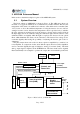
Figure 8. Layout of the digital filter.