
User`s guide


APDCAM User’s Guide
Page 13/32
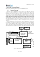
UDP packets and transmitted through the Ethernet connection to the PC. Communication
with the PC can be done via the UTP connection. If needed fibre optics communication is
also possible through the built-in media converter.
The ADC works all the time, therefore it is possible to perform some triggering opera-
tions inside the camera. One possibility is internal triggering, where the data acquisition
starts when the signal reaches a certain level. The trigger level can be set individually for
all 32 channels. Another possibility is detector protection from extended periods of over-
load. If the signals are above a certain level over a specified time the bias voltage of the
detector is switched off. Details of the data acquisition operation are given in Section 3.2.
The Control and Power Unit provides power for all the other units and controls the de-
tector infrastructure: detector bias voltage, temperature, calibration light, shutter, fans.
The detector bias voltage can be set by the user up to a factory set limit in the range of
400-500 V. The exact limit is dependent on the individual detector. There is also a mini-
mum recommended detector bias voltage of 200 V, below that the crosstalk through the
pixels causes excessive noise. The control card also controls the detector temperature by
cooling or heating it via a Peltier element. No computer intervention is needed for the
control, only parameters can be set from the PC.
Operation parameters of the camera are set by setting registers in the ADC or the con-
trol unit. For a description of the register tables see Sections 3.2 and 3.4.
The communication between APDCAM and the host PC is performed by a general
purpose Gigabit communication card. It communicates with the two internal units via an
internal bus. The register tables of the camera can be written or read by sending UDP
datagrams to the Gigabit card. Acquired data is also sent via this card.
3.2. Detector and analog electronics
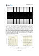
The detector has 32 identical Avalanche Photodiode elements (pixels) connected to a
common positive bias voltage. The arrangement and dimensions of pixels is shown in
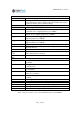
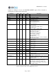
Figure 5. The mapping to/from detector pixels to data acquisition is shown in Table 4.
Figure 5. Detector dimensions and arrangement of pixels viewing the detector from
the front of the camera. All dimensions are in mm.