
User`s guide


APDCAM User’s Guide
Page 11/32
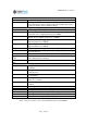
Controls
Power switch Switches the input power.
Reset button This depressed button can be operated with a pen or other pointed
device. Pressing it causes both the control unit and the data acquisi-
tion unit to return to factory default settings.
Connectors
Power connector Receives input 12 V DC power.
Clock in Reference TTL clock input. Synchronises clock base of APDCAM
to external source. (Signal standard 3.3 V CMOS)
Clock out Reference clock output. Can be used to synchronize clock base of
external device. (Signal standard 3.3 V CMOS)
Trigger in Data acquisition start trigger signal input.
(Signal standard 3.3 V CMOS)
Trigger out Outputs High level while data transmission is active.
(Signal standard 3.3 V CMOS)
Sample in Input resample clock. (Signal standard 3.3 V CMOS)
Opt Optional input-output. Can be selected among various internal sig-
nals in the factory.
Ethernet UTP connection to PC.
Optical Ethernet
UTP
UTP cable connection from Ethernet connector of APDCAM if
fibre communication is desired.
Optical Ethernet
fibre
Fibre data connection to PC
LEDs
Temp. Red light means temperature alarm. Some element of the camera is
overheated.
Overload Red light means overload condition occurred, detector bias voltage
is switched off.
Comm. Green light flashes when control communication occurs between
PC and camera
ADC Data acquisition module state: Green indicates normal state, red
means error condition.
Control Control module state: Green indicates normal state, red means error
condition.
Calib. Yellow light means calibration light is on.
Shutter Yellow light means shutter is open
HV Blue light means detector bias voltage is on.
Ext. Clock Green light means external reference clock signal is accepted.
Data out Green light indicates data output to PC.
Gbit Ethernet interface is operating at Gigabit speed.
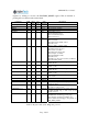
Table 3. List of controls, connectors and LED indicators of APDCAM.