APDCAM User’s Guide APDCAM Digital Avalanche Photodiode camera User’s Guide Version 1.01 Copyright © Adimtech Kft.
APDCAM User’s Guide CONTENTS 1. Introduction ................................................................................................................. 3 1.1. Using this document ............................................................................................. 3 2. Using APDCAM ......................................................................................................... 7 2.1. Power connection ..................................................................................
APDCAM User’s Guide 1. Introduction APDCAM is a 4x8 pixel Avalanche Photodiode Detector camera containing all detector infrastructure and data acquisition in one compact package. This type of detector is designed for special applications where low light level has to be measured with extreme high speed (up to several MHz). The detector pixels have large area (1.6x1.6 mm) compared to CCD sensors therefore they are easier to match to low f-number optics used in low light applications.
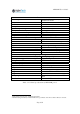
APDCAM User’s Guide Detector Avalanche Photodiode array Hamamatsu S8550 Array size 4x8 Pixel size 1.6 x 1.6mm Pixel pitch 2.3 mm Spectral response range 300 to 1000 nm Peak quantum efficiency 85% typical at 650 nm Detector Gain Typical 50, max 100 Temperature control range1 Typical 10...
APDCAM User’s Guide Data transmission Gigabit Ethernet over UTP and Fibre UDP, both directions Multimode, Duplex SC 2 MHz/12bit Power input Power input 12 V DC, max. 6A Power connector on power supply Lemo FFA.0S.302.CLAK68 Mechanical Size (L,W,H) 36*16*19 cm Weight without power supply 6.7 kg Data and control interface Communication format Fibre interface Max. data rate @ 32 channels3 Table 2. Technical specifications of APDCAM, part 2. 3 For typical PCIe computer card.
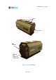
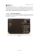
APDCAM User’s Guide Fans F-mount Fibre converter Backplate with connectors and indicators Figure 1. View of APDCAM.
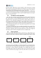
APDCAM User’s Guide 2. Using APDCAM 2.1. Power connection APDCAM is delivered with an external 12 V DC power adaptor. This unit has a replaceable power cord, please use one which matches your local mains outlet. The camera needs a single 12 V DC input, maximum current is 6A. The power adaptor is usable from 100 to 230 V mains voltage. 2.2. Operating environment Some effort might be needed in the setup to minimise noise pick up by the camera.
APDCAM User’s Guide munication a media converter is needed on the PC side. Adimtech recommends D-Link DMC-700SC media converters, which were extensively tested with APDCAM. On the camera side the media converter is included in the camera. Connect a short UTP cable between the camera UTP port and the camera Fibre module’s UTP port. Connect the optical cable to the camera fibre converter optical connector.
APDCAM User’s Guide the detector surface which can be set up via software to emit various levels of constant light on the detector, thus allowing calibration. The light level is not strictly proportional to the setting and the illumination of the detector is not uniform, therefore the calibration light cannot be used for calibrating the relative sensitivity of the pixels. The calibration light is also useful for setting up the optical system.
APDCAM User’s Guide bination with the internal trigger mode, as APDCAM can trigger itself on the incoming light signal. The camera can also produce an output trigger when the output is started. In the standard setup the data acquisition system timing is based on in internal quartz oscillator. However, if needed this can be replaced by an external clock signal to provide strictly synchronous operation between several cameras or other devices. 2.10.
APDCAM User’s Guide Power switch Reset button Power connector Clock in Clock out Trigger in Trigger out Sample in Opt Ethernet Optical Ethernet UTP Optical Ethernet fibre Temp. Overload Comm. ADC Control Calib. Shutter HV Ext. Clock Data out Gbit Controls Switches the input power. This depressed button can be operated with a pen or other pointed device. Pressing it causes both the control unit and the data acquisition unit to return to factory default settings. Connectors Receives input 12 V DC power.
APDCAM User’s Guide 3. APDCAM Reference Manual In this section a detailed description is given of the APDCAM system. 3.1. System Overview The block scheme of APDCAM is shown in Figure 4. The APD array detector is mounted on a copper tab which can be cooled/heated by a Peltier element. This way the temperature of the detector is stabilised at a reference value which can be somewhat (max ~15 C) below or above the ambient temperature.
APDCAM User’s Guide UDP packets and transmitted through the Ethernet connection to the PC. Communication with the PC can be done via the UTP connection. If needed fibre optics communication is also possible through the built-in media converter. The ADC works all the time, therefore it is possible to perform some triggering operations inside the camera. One possibility is internal triggering, where the data acquisition starts when the signal reaches a certain level.
APDCAM User’s Guide APD# A1 B1 C1 D1 E1 F1 G1 H1 Channel 1 2 3 4 5 6 7 8 Channel 18 20 21 23 25 27 28 30 APD# APD# A2 B2 C2 D2 E2 F2 G2 H2 Channel Channel 19 17 22 24 26 32 29 31 APD# APD# A3 B3 C3 D3 E3 F3 G3 H3 Channel Channel 15 13 16 10 8 6 1 3 APD# APD# A4 B4 C4 D4 E4 F4 G4 H4 Channel Channel 14 12 11 9 7 5 4 2 APD# G3 9 D4 17 B2 25 E1 H4 10 D3 18 A1 26 E2 H3 11 C4 19 A2 27 F1 G4 12 B4 20 B1 28 G1 F4 13 B3 21 C1 29 G2 F3 14 A4 22 C2 30 H1 E4 15 A3 23 D1 31 H2 E3 16 C3 24 D2 32 F2 Table
APDCAM User’s Guide The detector can be overloaded if high input light level is applied while the bias voltage is on. Although the detector and electronics is protected against overload under the most unfavourable conditions about 0.4W heat can be generated in the detector which might result in damage if present for an extensive time.
APDCAM User’s Guide registers by writing a code into the FACTORY_RESET register. This is identical to pressing the reset button at the camera back.
APDCAM User’s Guide Parameter R/W Offset (byte) Size (byte) ADC_TEST_MODE R/W 32 4 Value after start EEPROM FACTORY_RESET W 37 1 N/A BYTE_PER_SAMPLE R 40 4 N/A CLOCK_PLL_MULT CLOCK_PLL_DIV OFFSET R/W R/W R/W 46 47 48 1 1 64 EEPROM EEPROM EEPROM INT_TRIG_LEVEL R/W 112 64 EEPROM ACT_SAMPLE R 176 16 0 OVERLOAD_LEVEL R/W 192 2 EEPROM OVERLD_STATUS R/W 194 1 0 OVERLD_TIME TRIGGER_DELAY R/W R/W 195 197 2 4 EEPROM EEPROM FILTER_COEFF R/W 208 16 EEPROM Parameter
APDCAM User’s Guide At the beginning of the register map some registers describe the program and hardware versions and the unique serial number of the ADC board. After power-up the red-green bicolor ADC LED is lit green on the camera backplate. If the ADC unit encounters a fatal problem this LED is red. The DAQ unit is attached to the analog output signals at the backside of the detector housing. The 32 input channels have an analog bandwidth of about 3 MHz, the input voltage range is 0-2V.
APDCAM User’s Guide If the recursive filter is not to be used, COEFF_06=0. The impulse transfer function hi of the FIR filter should be calculated at 5 points using 1/fADC as the time resolution of the function. This can be done with some filter design toolbox. If the FIR filter is not to be used h1 is 1, all the others are 0. These hi coefficients should be normalised by their sums and multiplied by (4096-c)/8 to yield the coefficients of the FIR filter: h COEFF_0i = 5 i (4096-COEFF_06)/8, i=1...5.
APDCAM User’s Guide Figure 9. shows the simulated frequency transfer functions of the same cases. From these it is clear that the FIR filter is effective down to about 1/10-th of the ADC frequency. For lower frequency cutoffs it can be used in combination with the recursive filter. The recursive filter works at least down to 100 kHz, but at these low frequency cuts the FIR filter has no effect.
APDCAM User’s Guide By balancing the bit resolution, the channel number and the resampling rate the bandwidth of the data transmission can be used optimally. E.g. 10 MHz/12bit measurement is possible if one channel is selected in each block or 2 MHz/12bit if all 32 channels are working. 3.3.3. Triggering, overload protection The ADC measurement, digital filtering and resampling works continuously in APDCAM. but data output to the host is enabled only when data is needed.
APDCAM User’s Guide After the trigger event the data transmission can be delayed by setting the TRIGGER_ DELAY register which allows several ten second delay. After the TRIGGER_DELAY time data transmission starts and the Trigger Out signal goes to H on the backplate. At the same time the Data LED shows the active data transmission. Data from the measurement are continuously filling a ring buffer which size can be set in register RINGBUFSIZE.
APDCAM User’s Guide 3.4. Control unit The Control unit fulfils the following tasks: Detector bias voltage setting Detector temperature control, Shutter open/close, Calibration light setting, Temperature measurements, Fan control for regulating the camera internal temperature. The operating parameters of the Control unit can be found in its register table listed in Table 8 and Table 9. The unit stores its actual settings in an EEPROM non volatile memory.
APDCAM User’s Guide driven through a PID controlled. The weight factors of this can be set in the PID_P, PID_I, PID_D registers. For strongly different temperature settings these might need to be modified from the factory default. The actual Peltier current can be read in PELTIER_OUT. The operation of the temperature control can be suspended if all three PID_x registers are filled with 0. This means no current will be driven through the Peltier element.
APDCAM User’s Guide R/W Offset (byte) Size (byte) BOARD_VERSION MC_VERSION BIAS_MONITOR R R R 0 2 4 1 2 2 Value after start factory factory actual TEMP_ADC R 12 8 actual TEMP_DETECTOR TEMP_ANALOG R R 20 22 2 2 actual actual TEMP_DETHOUSE R 24 2 actual TEMP_PELTIER R 26 2 actual TEMP_CONTROL R 28 2 actual TEMP_BASE R 30 2 actual TEMP_DAQ R 40 2 actual PELTIER_OUT R 44 2 actual PID_P PID_I PID_D BIAS_SET R/W R/W R/W R/W 80 82 82 86 2 2 2 2 EEPROM EEPROM EEP
APDCAM User’s Guide R/W Offset (byte) Size (byte) SHUTTER_MODE R/W 128 1 Value after start EEPROM SHUTTER_STATE R/W 130 1 EEPROM FACTORY_RESET W 132 1 0 ERROR_CODE R 134 1 0 BOARD_SERIAL BIAS_MAX R R 256 258 2 2 factory factory Parameter Description Bit 0 controls shutter mode. 0: Shutter controlled by SHUTTER_STATE 1: Shutter controlled from Opt. connector if set up in factory. Bit 0 controls shutter state in manual mode. 0: closed, 1: open.
APDCAM User’s Guide 3.6. Software interface Control of APDCAM is performed using the CamControl.dll Dynamic Link Library for C++. To use the functions the CamControl.lib static library should be linked to the program. The DLL was compiled with Microsoft Visual Studio 2005 Professional Edition ENU Service Pack 1 (KB926601). Version 8.0.50727.762 (SP.050727-7600), Microsoft .NET Framework Version 2.0.50727. To use the binaries MS XP Service pack 1 should be installed.
APDCAM User’s Guide Declaration of DLL functions can be found in CamControl.h. Detailed use of the DLL calls is the following. open Declaration: CAMCONTROL_API int open(unsigned int ipAddress); Description: This call opens the sockets for communication. The ipAddress argument is the IP addres of the camera, each 8 bits correspond to one subnet address, eg. the default camera address is translated to: 10.123.13.
APDCAM User’s Guide SendTS Declaration: CAMCONTROL_API int SendTS(int *pStreams); Description: This call enables stream data input from APDCAM to the PC but does not provide the data storage. It should be noted that APDCAM sends data in four separate streams each transmitting data from 8 channels. (Provided they are enabled for transfer.
APDCAM User’s Guide TS0_Server.SetListeningPort(57000); TS0_Server.SetBuffer(lpMemReserved0, MEMORY_REQUESTED); HANDLE hEvent0 = CreateEvent(NULL, TRUE, FALSE, NULL); if (hEvent0 == NULL) throw new CExcp(0); TS0_Server.SetPacketSize(stream_1_packetsize + sizeof(CW_FRAME)); TS0_Server.SetNotification(requestedData0, hEvent0); TS0_Server.Reset(); if (requestedData0 != 0) { if (TS0_Server.
APDCAM User’s Guide 3.6.1. Received data memory map This section defines the memory map after data transfer has been completed to a buffer. Each stream has its own buffer, therefore normally 4 buffers should be processed after the measurement. Data from the DAQ Unit is packed into data packets which are extended with a header by the Gbit Ethernet Controller. The length of the data packet is specified in the call to SendTS(), most often it is set to 1440 bytes, what is the maximum size.
APDCAM User’s Guide Number of enabled channels 1 2 3 4 5 6 7 8 Resolution (bits) 8 12 14 1 2 3 4 5 6 7 8 2 3 5 6 8 9 11 12 2 4 6 7 9 11 13 14 Table 12. Number of bytes in a sample block for different numbers of enabled channels and resolution.