
Instruction manual


55
10 GB Communication
Version
1.0
3
& Control Card Instruction Manual
5.6 CAM Timer Instructions
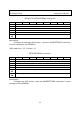
SETCTCONTROL instruction
Byte
7
6
5
4
3
2
1
0
1
-
2
Opcode
0x0
120
3
-
4
Length
0x0002
5
0
0
0
0
0
0
0
0
6
0
IT
ETF
ETR
Mode
S
A
Description:
Set the control register of the CAM Timer module. (Use the
SAVESETTINGS instruction to save changes to the EEPROM.)
A: 0/1 – Idle/Armed state
S: 0/1 – Manual Stop/Start
Mode: 00 – Return to Idle state after all the timers finish pulse
generation.
01 – Return to Armed state after all the timers finish pulse
generation.
10 – Return to Running state after all the timers finish pulse
generation.
ETR: 0/1 – External trigger rising slope disabled/enabled
ETF: 0/1 – External trigger falling slope disabled/enabled
IT: 0/1 – Internal trigger disabled/enabled
SETCTOUTPUT instruction
Byte
7
6
5
4
3
2
1
0
1
-
2
Opcode
0x0
12
1
3
-
4
Length
0x0002
5
Output Polarity
Output Enabled
6
Output in Armed state
Output in Idle
state
Description:
Set the output register of the CAM Timer module. (Use the
SAVESETTINGS instruction to save changes to the EEPROM.)