MDLMDL-DataManager™ Version 5.0 Reference Guide For use with the MicroDataLogger® data acquisition system. Updated June 2002 www.archenergy.
FCC Notice WARNING This equipment has been certified to comply with the limits for Class B computing devices, pursuant to Subpart J of Part 15 of FCC Rules. Only peripherals (Computer input/output devices, terminals, printers, etc.) certified to comply with the Class B limits may be attached to this computer. Operation with non-certified peripherals is likely to result in interference to radio and TV reception. (44 FR 59543. Oct. 16, 1979, as amended at 45 FR 24166. Apr.
License Agreement Please read this license agreement. If you do not agree to these terms, return the full product to Architectural Energy Corporation within thirty (30) days of delivery. This is a legal agreement between you, the end user, and Architectural Energy Corporation. The MDL-DataManager™ software program (the software) is licensed by Architectural Energy Corporation to the original customer and any subsequent transferee of the product for use only on the terms set forth here.
MicroDataLogger® Portable Data Acquisition System Standard Product Warranty Architectural Energy Corporation (AEC) warrants the MicroDataLogger portable data acquisition system and accessories to be free from defects in material and workmanship for a period of one year. This warranty is limited to repairing or replacing, at AEC’s option, any defective component, only when it is returned with an AEC Return Material Authorization number to AEC or to an AEC-designated repair facility.
MDL-DataManager™ Software and MicroDataLogger® data acquisition system Reference Guide Table of Contents Section Topic 1.0 Overview 1 2.0 Quick Start Guide Attaching Modules to the MicroDataLogger Unit LCD and Push Button Button Start/Stop Software Installation Connecting the MicroDataLogger to a Computer Configuring the MicroDataLogger Battery Capacity and Charging Estimated Battery Run Time Sensors with High Power Requirements Battery Run Time Test 2 2 2 3 3 3 3 4 5 6 6 3.
Section Topic 3.3 Table of Contents Page Graph Menu Commands (continued) Copy Graph to Clipboard The Mouse 21 21 3.4 Graph Analysis Features Integration and Statistical Analysis 22 22 3.5 View Menu Commands 23 3.6 Preferences Menu Commands Options Edit Modules List 23 24 24 3.7 Help Menu Commands 24 4.
MDL-DataManager™ Reference Guide Architectural Energy Corporation 1.0 Overview of the MicroDataLogger® System Architectural Energy Corporation (AEC) has created the MicroDataLogger® data acquisition system that is a portable, four-channel, battery-powered logger with associated sensors and accessories. The MicroDataLogger unit (MDL) is a generalpurpose microcomputer-based data logger with the following unique features.
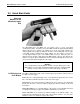
MDL-DataManager™ Reference Guide Architectural Energy Corporation 2.0 Quick Start Guide Attaching Modules to the MicroDataLogger Unit The MicroDataLogger unit (MDL) has four plug-in slots for sensor and signal conditioning modules. Facing the front of the MDL unit with the Liquid Crystal Display (LCD) at the top, these channels are numbered 1 to 4 from left to right.
MDL-DataManager™ Reference Guide Architectural Energy Corporation Note: If your MDL does not have firmware version 1.07 or higher, please call to order a firmware upgrade for your MDL. Firmware version 1.08 is standard on Model 202 MicroDataLogger units. Once a display mode is activated, it will continue through its display sequence and then go back to sleep. To cancel and exit a display mode, press the button once. Button Start/Stop The pushbutton can also be used to override the programmed Start Time.
MDL-DataManager™ Reference Guide Architectural Energy Corporation Configuring the The MicroDataLogger unit must be programmed for a particular data collection MicroDataLogger application before it can be used. This process is called configuration. To configure the logger, use the following procedure: 1. First, plug in the appropriate modules if you would like the software to automatically configure the channels with the proper modules.
MDL-DataManager™ Reference Guide Architectural Energy Corporation Recharging time varies depending on the condition of the battery, but 8 to12 hours (overnight) is the maximum time required. The charger is designed to function at room temperature (65-75 degrees F) and will not charge properly in cold or hot environments. The red LED indicator on the charger will light brightly when first connected to a discharged battery.
MDL-DataManager™ Reference Guide Architectural Energy Corporation battery will appear to be about the same as a new one, but its capacity and run time will be less. The MDL’s battery is designed to maintain 80% of its new capacity after 200 charge/discharge cycles. Low ambient temperatures (0°F) will decrease capacity about 30%. In addition, the self-discharge rate of the battery at room temperature is about 5% per month.
MDL-DataManager™ Reference Guide Architectural Energy Corporation After the test, remember to recharge the battery for eight or more hours before using or storing the MDL. Section 2.
MDL-DataManager™ Reference Guide Architectural Energy Corporation 3.0 MDL-DataManager™ Software MDL-DataManager software operates in the Windows operating system. Software installation instructions can be found in Section 2. When MDL-DataManager software is accessed, a title screen is shown, followed by a blank screen with the following menu commands shown across the top tool bar: File Logger Graph View Preferences Help Each of the six main menu commands are discussed in detail.
MDL-DataManager™ Reference Guide Architectural Energy Corporation Edit Log File At times, it is necessary to edit an MDL log file while still maintaining the MDL *.log format. MDL log files can be edited by selecting Edit Log File under the File menu. When this menu option is selected, a standard file dialog is displayed to allow the selection of the file to be edited. When the file is selected, a new file name is suggested, usually by adding “_1” to the original file name.
MDL-DataManager™ Reference Guide Print Configuration File Architectural Energy Corporation Configuration files are saved while in the Configure MDL screen. The command File– Print Configuration File sends a MDL logger configuration file to the printer. First, the file dialog box Print a Configuration File is displayed. Select the MicroDataLogger configuration file to print. Click OK to print. This option is useful for documenting your monitoring setups.
MDL-DataManager™ Reference Guide Architectural Energy Corporation Note: If File–Use Existing Config from the File menu is chosen, the software will fill in all fields using the information stored in the existing file. However, if there are modules plugged into the logger and there is a difference between the physical module and the module type in the configuration file, a warning dialog will be displayed to ask if you want the contents of the file to override the actual configuration.
MDL-DataManager™ Reference Guide Architectural Energy Corporation filled in based on the configuration information stored in the MicroDataLogger unit (MDL) from the last time it was configured. If the File–Use Existing Config is initially selected, the Start Date and Start Time, Duration, Sample Interval and Samples To Average fields are filled in based on the information previously saved in a configuration file. Start Date and Start Time.
MDL-DataManager™ Reference Guide Architectural Energy Corporation Button Start/Stop The MicroDataLogger unit has the capability of being started or stopped in the field manually by holding the push button in for five seconds. This feature is only available if the logger was configured with the Button Start/Stop Enable option selected. If a manual start in the field is desired, the Button Start/Stop Enable check box needs to be clicked on in the Run Time Parameters Group box.
MDL-DataManager™ Reference Guide Architectural Energy Corporation Scale Buttons There are four Scale buttons, one for each channel. These are enabled only if a User Configurable type of module is installed, such as a 0-5 VDC input module or a pulse input module, for example. When a user configurable module is installed, click the Scale button to open the module Configuration Parameters window. Configuration Parameters. User configurable modules can be configured with the following parameters.
MDL-DataManager™ Reference Guide Architectural Energy Corporation Scale and Offset A Wizard is provided that is accessed by clicking the Slope and Offset Wizard button. Wizard Different screens are displayed depending on the type of user-configurable module attached to the logger. An example window that requests user-defined parameters for Slope and Offset calculations is shown below. The Wizard that appears is based on the module selected.
MDL-DataManager™ Reference Guide Architectural Energy Corporation Read Config. When the Read Config button is clicked, the software updates all the fields on the Configure MDL window with the configuration information stored in the MDL. The action is identical to that which occurs when you first enter the Configure MDL window. This option can be used to read a new MDL’s configuration without having to exit the Configure MDL window. This allows multiple loggers to be configured more quickly. Send Config.
MDL-DataManager™ Reference Guide Architectural Energy Corporation The Logger–Real Time Reading Command displays the current channel readings and the status of the MicroDataLogger unit. The readings are updated approximately every two seconds. To close this screen, click the Close button. Another way to read real-time readings is to push the MDL pushbutton two times and read the real time readings on the logger display.
MDL-DataManager™ Reference Guide Architectural Energy Corporation The MicroDataLogger unit will sound a tone when it begins transferring data. As the data is retrieved, a Percent Complete display will indicate progress. At about 90% complete, the MDL will sound a tone, which indicates that the data file has been successfully transferred to the host computer. The program then will run for a few moments more to convert the data and store it in the file.
MDL-DataManager™ Reference Guide Architectural Energy Corporation saved, imported into other programs using the clipboard, and printed. Follow these steps when Graph—–New Graph Definition is selected to create or edit a graph definition. 1. Select the desired MicroDataLogger data file in the file list box. When you select the file by clicking once on it, the data channels in the selected file will be listed in the "Channels" list box. 2.
MDL-DataManager™ Reference Guide Architectural Energy Corporation Open Graph When Graph–Open Graph Definition is selected from the menu, a file dialog box is Definition displayed showing the available graph definition files. Graph definition files end in the extension *.grf. The Files shown in the Open an existing Graph Definition File window contain pointers (links) to the data files used to create a graph, not the data itself.
MDL-DataManager™ Reference Guide Architectural Energy Corporation Clipboard button to complete the operation. The data can now be pasted into another application such as Microsoft® Word or Excel. One Plot. When data are plotted on a single plot, up to 25 data streams from any combination of data files can be viewed. To facilitate viewing data with different units or vastly different values, data can be assigned to either the left (Y1) or right (Y2) axis.
MDL-DataManager™ Reference Guide Architectural Energy Corporation When the mouse pointer is dragged across the screen when the left mouse button is held down, a rectangle will be displayed that shows the area that will be included in the new graph. Clicking on the Unzoom button returns the graphs to their original scale and appearance. Analysis Mode: If the Analysis Mode radio button is selected, the mouse is in analysis mode. In Analysis Mode, the mouse is used to select a time region for analysis.
MDL-DataManager™ Reference Guide Architectural Energy Corporation Number of Samples. The number of samples included in the selected region. Area. The area is derived by integrating under the curve, using the 0 on the Y-axis as the lower bound. The integration algorithm used is Simpson’s Method. If only a single data point is selected, the area is undefined. Min. The minimum Y value for the selected region. Max. The maximum Y value for the selected region. Avg. The average Y value for the selected region.
MDL-DataManager™ Reference Guide Architectural Energy Corporation Options This Preferences menu option displays a window with the following tabs for setting various options within the software: Comm Port/Modem Configuration. Selecting Preferences–Options, Comm Port/Modem opens a window that provides a choice of communications port connection for a serial interface with a MicroDataLogger unit as well as phone and modem settings for MDL-DataManager software to store.
MDL-DataManager™ Reference Guide Architectural Energy Corporation 4.0 MDL-Remote™ Application AEC enhanced the MicroDataLogger data acquisition system (MDL) by adding remote access capabilities. Remote access allows MDL users to automatically retrieve data from loggers using a phone line and download data to a computer while the equipment is still installed in the field. The ability to easily and quickly access data from a remote site is the main benefit of this enhancement.
MDL-DataManager™ Reference Guide Architectural Energy Corporation Since you may want to automatically download the MDL for the duration of the data collection, use the following suggested run time parameters: Memory Write Enable If you wish to be able to collect data indefinitely, check this box. (Recommended only if you're going to be using MDL-DataRetriever.
MDL-DataManager™ Reference Guide Architectural Energy Corporation ! Check the "Use Modem for all Logger Actions" check box to enable the software to use the modem. ! Set the number of "Dial Retries" to the maximum number of times you wish the software to try to reconnect with the remote modem. ! Click OK to close this dialog.
MDL-DataManager™ Reference Guide MDLDataRetriever Software Architectural Energy Corporation Item Number Description Telephone number for connecting with the remote modem. The phone number may include dashes and parentheses, commas for pauses and any other codes that may be required for your phone system. Description An optional description associated with the selected number.
MDL-DataManager™ Reference Guide Architectural Energy Corporation 5.0 Trouble Shooting If you experience problems with your MicroDataLogger unit (MDL), MDLDataManager software, or MDL-DataRetriever software, there are several potential sources of the problem. The following is a table of potential MDL problems, and the appropriate action to take to correct the problem.
MDL-DataManager™ Reference Guide Architectural Energy Corporation decimal digits will cause asterisks (****) to appear in the MicroDataLogger unit’s display. Battery voltage runs down The battery will slowly self-discharge while a logger is sitting unused over time. While being stored, the battery should be recharged every two months. If the battery voltage runs down over a very short period of time, the battery may need to be replaced.
MDL-DataManager™ Reference Guide Architectural Energy Corporation 6. With MDL-DataManager versions prior to 4.0, some virus scan applications caused com port communication problems. Although no current virus scan applications are known to cause PC/MDL communication problems, it is not possible to state that these problems could not recur due to ongoing virus scan update releases.
MDL-DataManager™ Reference Guide Architectural Energy Corporation Appendix A – Module Wiring Connections Architectural Energy Corporation (AEC) stocks signal conditioning modules for use with a wide array of AEC-supplied or third-party sensors. These different signal conditioning modules allow the MicroDataLogger unit (MDL) to connect to nearly any sensor or meter on the market based on the sensor or meter output signal.
MDL-DataManager™ Reference Guide Architectural Energy Corporation Module Wiring Diagrams MicroDataLogger ® Wiring Diagrams for 5 volt, 10 volt & 20 mA Modules VDC-19-3, VDC-29-3, ADC-33-3 Revised: 6/25/2000 Note: 10 volt module wired the same as 5 volt – + 1 5 volts DC VDC-19-3 2 5 volts DC VDC-19-3 power supply + power TRANSDUCER – power + signal 2-wire externally powered – signal + power TRANSDUCER 3-wire MDL powered + signal – signal 3 5 volts DC VDC-19-3 4 20 mA DC ADC-33-3 and powe
MDL-DataManager™ Reference Guide Architectural Energy Corporation Appendix B – Calculating Scale Factors Architectural Energy Corporation (AEC) stocks signal conditioning modules for use with a wide array of AEC-supplied or third-party sensors. These different signal conditioning modules allow the MicroDataLogger unit (MDL) to connect to nearly any sensor or meter on the market based on the sensor or meter output signal.
MDL-DataManager™ Reference Guide Architectural Energy Corporation Appendix C – MicroDataLogger® Specifications Channel Capacity Four universal input/output channels accept both analog and digital signal conditioning modules. User Interface 16 characters by two line alphanumeric display, push-button switch and audible signal tone. Module Auto ID Automatic logger programming of module/sensor signal type and range information.