
user manual
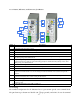
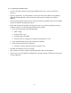

block unscrew the terminal screws on the block and insert the ends of the appropriate wires into
each opening. Tighten the terminal screws. Pins A and B are the 709.1 LON channel port pins.
For FTT-10 transceivers, use the A and B pins. e pins are polarity insensitive. For RS-485
transceivers use the A and B pins appropriately and insert the RS-485 ground lead into the
terminal block pin with the (ground) symbol next to the pin labeled A. ere are two power
input pins labeled (logic ground) and 5VDC. e GRouter4A requires regulated 5 Volt DC
positive on the 5VDC pin. Attach the ground pin from the power supply to the pin labeled .
e power input is polarity sensitive but does have reverse polarity protection. If aer powering
up the 5V input, the power LED does not light up, disconnect power and check the polarity of the
input power wires before recycling power. Applying a reverse voltage for an extended time period
may damage the GRouter4.
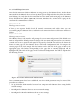
Fig.1.13: Front terminal block detail with standard connector
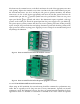
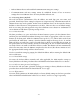
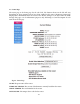
Fig.1.14: Front terminal block detail with optional pluggable connectors
1.8.4. FTT-10 XCVR LonTalk Network Termination
When using an FTT-10 XCVR, the network wiring should be terminated or performance may
suer. is is especially true for long wire runs or noisy environments. Typically an external
terminator is used. e GRouter4, however, does have an optional internal terminator for those
applications where it is desirable or convenient to terminate at the router. When the optional
-22-