
User`s guide

System Installation
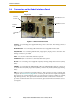
24 Adept Cobra i600/i800 Robot User’s Guide, Rev G
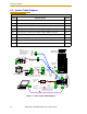
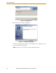
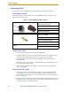
3.2 System Cable Diagram
Figure 3-1. iCobra System Cable Diagram
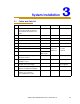
Installation Procedure
Step Step Description Part(s)
1 Connect AIB XPANEL cable to XPANEL on Interface Panel. A
2 Verify XUSR jumper plug is installed on XUSR connector. B
3 Connect Front Panel cable to Front Panel and XFP connector. C, D
4 If no T2, install XMCP jumper or T1/T2 bypass plug. Skip to 5. E, F
4a If you have T2, connect T1/T2 adapter cable to XMCP connector. G, H
5 Connect user-supplied ground. See Section 3.8 on page 34 for locations. -
6 Connect 200-240 VAC to AC Input on Interface Panel, secure with clamp. J
7 Connect 24 VDC to DC Input on Interface Panel. (May need AC cable.) K, L
8 Connect null modem serial cable to Interface Panel and serial port on PC. M
Adept Cobra
i600/i800 Robot
24 VDC, 6 A
Power Supply
200-240 VAC
10 A
single-phase
AC Power
Cable
DC Power
Cable
Front Panel
Cable
Front Panel
User-Supplied PC
running Adept ACE
T1/T2 Adapter
Cable
XMCP Jumper Plug
XMCP
XFP
XUSR
XUSR
Jumper
Plug
AIB
XPANEL
Cable
Robot Interface
Panel
XUSR for:
- User E-Stop/Safety Gate
- Muted Safety Gate
- Jumper plug required
when not used
RS-232 Null Modem Cable
for Robot to PC Connection
T1/T2 Bypass Plug
User-Supplied
Ground Wire
GND
XSLV
1
2
SmartServo
RS-232
XPANEL
AC INPUT
(200-240 VAC 1&)
+24V
DC INPUT
(24VDC)
XIO
GND
XSLV
1
2
SmartServo
RS-232
XPANEL
AC INPUT
(200-240 VAC 1&)
+24V
DC INPUT
(24 VDC)
XIO
T2 Pendant (optional)
Either T1/T2 Bypass Plug or XMCP Jumper Plug
must be installed if T2 is not used
2
3
4a
A
B
E
F
G
4a
4
4
1
5
6
7
8
8
J
K
M
D
H
C
L
3
85 - 264 VAC
Universal
Input