
Specifications


Chapter 4 - AdeptVision sAVI Option
74 Adept SmartController User’s Guide, Rev. H
4.5 Camera Cable Pin and Signal Information
This section provides the pin and signal information for the connectors and cables
associated with the AdeptVision product.
• Table 4-1 describes the Hirose connector on the breakout cables.
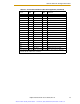
• Table 4-2 on page 75 describes the Strobe and Power connector on the standard
Four-Camera Breakout Cable.
• Table 4-3 on page 76 describes the 10-meter camera extension cable.
• Table 4-4 on page 77 describes signal information between the 44-pin connector
and the camera connectors for the two-camera breakout cable.
• Table 4-5 on page 78 describes signal information between the 44-pin connector
and the camera and strobe/power connectors for the four-camera breakout cable.
The table is organized by camera number.
• Table 4-6 on page 80 contains information similar to Table 4-5, but it is organized
numerically by the 44-pin connector.
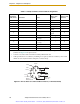
Table 4-1. Breakout Cable Camera Connector Pin Assignments (RS-170)
Pin Function Notes
1Power return
2+12 V power to camera
3 Shield (video)
4Video from camera
5Shield (Hd)
6 Hd (horizontal drive) to camera
7 Vd (vertical drive) to camera
8 Shield (Clock) from camera (camera 1 & 2 only)
9 Clock from camera (camera 1 & 2 only)
10 not connected
11 not connected
12 Shield (Vd)
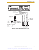
12-Pin Hirose Female Jack, HR10A-10J-12S
This connector will normally be connected to the camera using a 10-meter camera extension cable.
For special applications, this connector will mate with a Hirose Male Plug HR10A-10P-12P
(user-supplied) or similar plug. See Figure 4-4 on page 76 for pin locations.
Artisan Scientific - Quality Instrumentation ... Guaranteed | (888) 88-SOURCE | www.artisan-scientific.com