
Specifications


Chapter 3 - SmartController Operation
60 Adept SmartController User’s Guide, Rev. H
NOTE: The input current specifications are provided for reference;
voltage sources are typically used to drive the inputs.
NOTE: When the program task priorities are properly set, there is a 2 ms
maximum latency for fast inputs 1001 to 1004 when used with the V
+
INT.EVENT instruction.
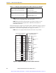
In the following figure, example 1 shows inputs (1001 to 1004) with a negative common,
example 2 shows inputs (1005 to 1008) with a positive common, and example 3 shows
inputs (1009 to 1012) with an independent power supply (no common).
NOTE: These are examples. Either method can be used on any channel.
Figure 3-6. Digital Input Wiring Examples (XDIO Connector)
Turn-on response time (hardware)
Software scan rate/response time
5 µsec maximum
16 ms scan cycle/
32 ms max response time
Turn-off response time (hardware)
Software scan rate/response time
5 µsec maximum
16 ms scan cycle/
32 ms max response time
Table 3-11. DIO Input Circuit Specifications (XDIO connector) (Continued)
Customer power
supply
Example 1
Example 2
Example 3
Customer power
supply
Signal 1001
Signal 1002
Signal 1003
Signal 1004
Signal 1005
Signal 1006
Signal 1007
Signal 1008
Signal 1009
Signal 1010
Signal 1011
Signal 1012
+
–
+
–
+
–
+
–
+
–
+
–
Adept-Supplied Equipment Customer-Supplied Equipment
(Typical Examples)
(equivalent circuit)
1
2
3
4
5
6
7
8
9
10
11
12
13
14
15
16
17
18
19
20
21
22
23
24
+
–
+
–
+
–
+
–
+
–
+
–
+
–
+
–
+
–
+
–
+
–
+
–
XDIO Connector on SmartController - Inputs
Sourcing
Sinking
Artisan Scientific - Quality Instrumentation ... Guaranteed | (888) 88-SOURCE | www.artisan-scientific.com