
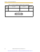
Specifications


Chapter 3 - SmartController Operation
56 Adept SmartController User’s Guide, Rev. H
Remote Manual Mode
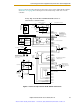
The Front Panel provides for a Manual Mode circuit (see Figure 3-4 on page 53, Tab le 3 -7
on page 49, and Table 3-8 on page 51, and your robot manual for further details about the
customer Remote Manual Mode circuitry).
The Adept Front Panel, or the customer-supplied panel, must be incorporated into the
robot workcell to provide a “Single Point of Control” (the pendant) when the controller is
placed in Manual mode. Certain workcell devices, such as PLCs or conveyors, may need
to be turned off when the operating mode switch is set to Manual mode. This is to ensure
that the robot controller does not receive commands from devices other than from the
pendant, the single point of control.
If the user needs to control the Manual/Automatic mode selection from other control
equipment, then a custom splitter cable or complete replacement of the Adept Front Panel
may be required. See Figure 3-5 on page 54 for the Front Panel schematic. In this situation,
a pair of contacts should be wired in series with the Adept Front Panel Manual/Automatic
mode contacts. Thus, both the Adept Front Panel and the customer contacts need to be
closed to allow Automatic mode.
User Manual/Auto Indication
Two pairs of pins on the XUSR connector (pins 9, 22 and 10, 23) provide a voltage-free
contact to indicate whether the Front Panel and/or remote Manual/Automatic switches
are closed. The user may use these contacts to control other mechanisms (for example,
conveyor, linear modules, etc.) when Manual mode is selected. The load on the contacts
should not exceed 40 VDC or 30 VAC at a maximum of 1 A.
User High Power On Indication
In the CAT-3 version of the SmartController (see page 23), a V
+
-controlled, normally-open
relay contact, on the XDIO connector (pins 45, 46, see Table 3-13 on page 63), will close
when High Power has been enabled. The user can use this feature to power an indicator
lamp or other device, that signals High Power is On. The limit on these contacts is 1 A at
30 VDC or 30 VAC.
CAUTION: If you want the cell gate to always cause a
robot shutdown, wire the gate switch contacts in series
with the user E-Stop inputs. Do not wire the gate switch
into the muted safety gate inputs.
WARNING: Do not wire customer-supplied
Manual/Automatic contacts in parallel with the Adept
Front Panel switch contact. This would violate the “Single
Point of Control” principle and might allow Automatic
(high-speed) mode to be selected while an operator is in
the cell.
Artisan Scientific - Quality Instrumentation ... Guaranteed | (888) 88-SOURCE | www.artisan-scientific.com