
Specifications


Connecting Customer-Supplied Safety and Power-Control Equipment
Adept SmartController User’s Guide, Rev. H 49
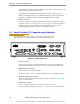
3.7 Connecting Customer-Supplied Safety and Power-Control
Equipment
Connecting Equipment to the System
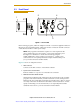
The connection of the customer-supplied safety and power-control equipment to the
system is done through the XUSR and XFP connectors on the SmartController. The XUSR
connector (25-pin) and XFP (15-pin) connector are both female D-sub connectors located
on the front panel of the SmartController. Refer to Table 3-7 for the XUSR pin-out
descriptions. Refer to Table 3-8 on page 51 for the XFP pin-out descriptions. See Figure
3-4 on page 53 for the XUSR wiring diagram.
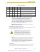
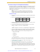
Table 3-7. Contacts Provided by the XUSR Connector
Pin
Pairs
Description Comments
Shorted if
NOT Used
Voltage-Free Contacts Provided by Customer
1, 14
User E-Stop CH 1 (mushroom
push-button, safety gates, etc.)
N/C contacts
Yes
2, 15
User E-Stop CH 2 (same as pins
1, 14)
N/C contacts
Yes
3, 16
Line E-Stop (used for other robot or
assembly line E-Stop
interconnection. Does not affect
E-Stop indication (pins 7, 20))
N/C contacts
Yes
4, 17 Line E-Stop (same as pins 3, 16) N/C contacts Yes
5, 18
Muted safety gate CH 1 (causes
E-Stop in Automatic mode only)
N/C contacts
Yes
6, 19
Muted Safety Gate CH 2 (same as
pins 5, 18)
N/C contacts
Yes
Voltage-Free Contacts provided by Adept
7, 20
E-Stop indication CH 1 Contacts are closed when
Front Panel, pendant, and
customer E-Stops are not
tripped
8, 21
E-Stop indication CH 2 (same as
pins 7, 20)
Contacts are closed when
Front Panel, pendant, and
customer E-Stops are not
tripped
9, 22
Manual/Automatic indication CH 1 Contacts are closed in
Automatic mode
10, 23
Manual/Automatic indication CH 2 Contacts are closed in
Automatic mode
Artisan Scientific - Quality Instrumentation ... Guaranteed | (888) 88-SOURCE | www.artisan-scientific.com