
Specifications


Chapter 3 - SmartController Operation
40 Adept SmartController User’s Guide, Rev. H
(10356-10400) to transition from the MCP’s circular plastic connector (CPC) to the
SmartController’s 15-pin D-sub connector.
The MCP-III (P/N 90332-48050) also requires the special 6' adapter cable. In
addition, the MCP-III must use a small MCP-III adapter module (10356-10370)
plugged into the XMCP connector before the adapter cable is attached.
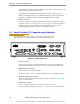
13. 24 VDC connectors
Connect power from a customer-supplied 24 VDC power supply to the XDC1
connector (see the “Connecting Power” section on page 32). If using an sDIO or
an sMI6, connect a separate cable from the unused XDC connector on the
SmartController to the XDC1 connector on the sDIO or sMI6.
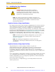
3.2 SmartController CX Connectors and Indicators
The SmartController CX has all the of connectors and indicators of the
SmartController CS, plus the additional ones described in this section.
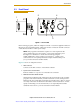
Figure 3-2. SmartController CX
1. Camera connector
This connector is present when the AdeptVision sAVI option is installed. The
camera breakout cables connect here. See Chapter 4 for complete information.
2. IEEE-1394 ports 2.1 and 2.2
These ports are reserved for future use.
Do not use ports 2.1 or 2.2 to connect Adept Smart Servo-compatible products.
3. RS-232-1 and RS-232-2 connector
These are additional RS-232 serial ports for general use. See Section 3.5 on page
44 for more information.
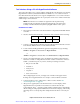
4. Belt Encoder connector
This is a 15-pin D-Sub connector for up to two belt encoders in a
conveyor-tracking installation. See Section 3.9 on page 65 for more information.
R
ON
SmartServo IEEE-1394
1234
SF ES HD
SW1
1.1 1.2 2.1 2.2
OK
123
XDIO
LANHPE
OFF
XSYS
CAMERA
Eth 10/100
XUSR
Device Net
XFP
RS-232/TERM
RS-232-1
XMCP
BELT ENCODER
SmartController CX
-+ -+
RS-422/485
XDC1 XDC2
24V 5A
*S/N 3562-XXXXX*
RS-232-2
Artisan Scientific - Quality Instrumentation ... Guaranteed | (888) 88-SOURCE | www.artisan-scientific.com