
User`s guide


Chapter 6: Optional Equipment Installation
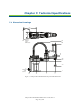
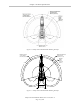
NOTE:This 6 mm User Air connector and the 6 mm User Air connector at the top
of Figure 6-2 are not available for other uses after this modification.
16.
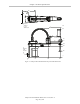
Reinstall the Joint 1 cover, taking care to ensure that all tubing is inside the cover and
nothing gets crimped or pinched while pushing the cover into position. Reinstall four
screws to secure the cover. Tighten the screws to 1.6 N·m (14 in-lb) of torque.
17.
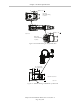
Reinstall the cable strap plate that you removed earlier in the procedure.
18.
Raise the eAIB chassis to the closed position and tighten the securing screw.
19.
Reinstall the outer link cover and tighten the screws to 1.6 N·m (14 in-lb) of torque.
20.
Connect the factory air supply to the 6 mm User Air connector.
For the non-IP-65 robot, this is the air connector just modified.
21.
Select Signal 3001 and Signal 3002 to activate the solenoids one at a time.
WARNING:Disconnect robot air pressure until this test
has been done to prevent unsecured pneumatic lines
from accidentally injuring personnel.
Adept Cobra ePLC600/800 Robot, User’s Guide, Rev A
Page 81 of 108