
User`s guide


Chapter 6: Optional Equipment Installation
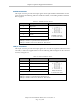
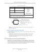
Table 6-5. ESTOP Connector
Pin # Description Pin Location
1
ESTOP_INPUT
ESTOP Connector
as viewed on robot
2 24 V
Mating Connector:
AMP/Tyco #172165-1, 2-pin Mini-Universal Mate-N-Lock
AMP/Tyco #770985-1, Pin Contact, Mini-Univ. Mate-N-Lok
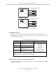
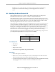
Pin 1
Pin 2
User-supplied normally-closed contact.
Can be connected to a break-away sensor
to cause an E-Stop condition when circuit
is open.
Note: This function is disabled by default - it must
be enabled in software.
Typical ESTOP
Connector Circuit
Figure 6-7. Internal E-Stop Connector Circuit
NOTE:This circuit will trigger an emergency stop of the local robot only. It does not
link to the E-Stop chain.
Procedure to Enable the Break-away E-Stop Function
To enable the Break-away E-Stop function, you have to use the Adept ACE software to change
the default configuration:
NOTE:When the Break-away E-Stop function has been enabled, you must connect
a normally-closed circuit to pins 1 and 2 of the ESTOP connector, as described
above. If this is not done, the system will be in an E-Stop condition and you will
not be able to enable power.
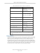
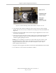
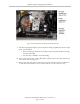
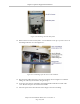
6.5 Mounting Locations for External Equipment
Three locations are provided for mounting user’s external equipment on the robot arm. The
first location is on the J1 Harness Support (top side of the inner link), a second is on the top
side of the outer link, and a third is on the bottom side of the outer link. Each location has a
set of four tapped holes. See External Tooling on Top of Robot Arm on page 86 and External
Tooling on Underside of Outer Link on page 86 for the dimensions.
Adept Cobra ePLC600/800 Robot, User’s Guide, Rev A
Page 76 of 108