
User`s guide

Chapter 4: System Operation
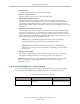
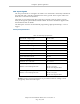
Typical Input Wiring Example
Adept-Supplied Equipment
User-Supplied Equipment
Signal 1001
Part Present Sensor
4
Signal 1002
Feeder Empty Sensor
5
Signal 1003
Part Jammed Sensor
6
Signal 1004
Sealant Ready Sensor
7
Signal 1005
8
Signal 1006
+24V
GND
9
Bank 1
Common
Bank 2
Common
3
2
1
Signal 1007
13
Signal 1008
14
Signal 1009
15
Signal 1010
16
Signal 1011
17
Signal 1012
18
12
GND
10
+24V
11
Wiring
Terminal
Block
Typical User
Input Signals
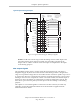
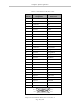
Note: all Input signals
can be used for either
sinking or sourcing
configurations.
Bank 1 configured for
Sinking (NPN) Inputs
Bank 2 configured for
Sourcing (PNP) Inputs
Input Bank 2 Input Bank 1
XIO Connector – 26-Pin Female D-Sub
(equivalent circuit)
Figure 4-5. Typical User Wiring for XIO Input Signals
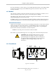
NOTE:The OFF state current range exceeds the leakage current of XIO outputs. This
guarantees that the inputs will not be turned on by the leakage current from the
outputs. This is useful in situations where the outputs are looped-back to the inputs
for monitoring purposes.
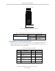
XIO Output Signals
The eight digital outputs share a common, high side (sourcing) driver IC. The driver is
designed to supply any kind of load with one side connected to ground. It is designed for a
range of user-provided voltages from 10 to 24 VDC and each channel is capable of up to 0.7 A
of current. This driver has overtemperature protection, shorted load protection, and is current
limiting. In the event of an output short or other overcurrent situation, the affected output of
the driver IC turns off and back on automatically to reduce the temperature of the IC. The
driver draws power from the primary 24 VDC input to the robot through a self-resetting
polyfuse.
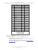
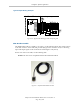
The outputs are accessed through direct connection to the XIO connector (see Table 4-5).
Optionally, use the XIO Termination Block. See the documentation supplied with the
termination block for details.
Adept Cobra ePLC600/800 Robot, User’s Guide, Rev A
Page 46 of 108