
User`s guide

Chapter 4: System Operation
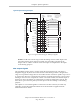
XIO Input Signals
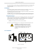
The 12 input channels are arranged in two banks of six. Each bank is electrically isolated from
the other bank and is optically isolated from the robot’s ground. The six inputs within each
bank share a common source/sink line.
The inputs are accessed through direct connection to the XIO connector (see the previous
table), or through the optional XIO Termination Block. See the documentation supplied with
the termination block for details.
The XIO inputs cannot be used for REACTI programming, high-speed interrupts, or vision
triggers.
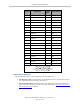
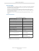
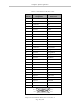
XIO Input Specifications
Table 4-6. XIO Input Specifications
Operational voltage range 0 to 30 VDC
OFF state voltage range 0 to 3 VDC
ON state voltage range 10 to 30 VDC
Typical threshold voltage V
in
= 8 VDC
Operational current range 0 to 7.5 mA
OFF state current range 0 to 0.5 mA
ON state current range 2.5 to 7.5 mA
Typical threshold current 2.0 mA
Impedance (V
in
/I
in
) 3.9 kΩ minimum
Current at V
in
= +24 VDC I
in
≤ 6 mA
Turn on response time (hardware)
Software scan rate/response time
5 µsec maximum
16 ms scan cycle/
32 ms max response time
Turn off response time (hardware)
Software scan rate/response time
5 µsec maximum
16 ms scan cycle/
32 ms max response time
NOTE:The input current specifications are provided for reference. Voltage sources
are typically used to drive the inputs.
Adept Cobra ePLC600/800 Robot, User’s Guide, Rev A
Page 45 of 108