
User`s guide

Chapter 4: System Operation
Cobra ePLC600/ePLC800 Robot
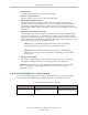
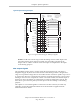
XIO Connector
12 Input signals: 1001 to 1012
8 Output signals: 1 to 8
Figure 4-4. Connecting Digital I/O to the System
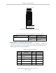
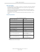
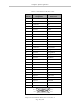
Table 4-4. Default Digital I/O Signal Configuration, Single Robot System
Location Type Signal Range
Robot 1 XIO connector Inputs 1001–1012
Outputs 0001–0008
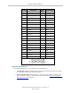
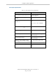
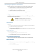
Using Digital I/O on Robot XIO Connector
The XIO connector on the robot interface panel offers access to digital I/O, 12 inputs and 8
outputs. These signals can be used to perform various functions in the workcell. See the
following table for the XIO signal designations.
Table 4-5. XIO Signal Designations
Pin No. Designation
Signal
Bank
Signal Number
1 GND
2 24 VDC
3 Common 1 1
4 Input 1.1 1 1001
5 Input 2.1 1 1002
6 Input 3.1 1 1003
Adept Cobra ePLC600/800 Robot, User’s Guide, Rev A
Page 43 of 108