
User`s guide


Chapter 3: System Installation
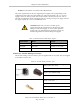
Recommended crimping tool, Molex Hand
Crimpers
Molex P/N 63811-0400
Digi-Key P/N WM9907-ND
NOTE:The 24 VDC cable is not supplied with the system, but is available in the
optional Power Cable kit. See Table 3-1.
Procedure for Creating 24 VDC Cable
1.
Locate the connector and pins shown in Table 3-4.
2.
Use 14-16 AWG wire to create the 24 VDC cable. Select the wire length to safely reach
from the user-supplied 24 VDC power supply to the robot base.
3.
Crimp the pins onto the wires using the crimping tool.
4.
Insert the pins into the connector. Confirm that the 24 V and 24 V return wires are in
the correct terminals in the plug.
5.
Prepare the opposite end of the cable for connection to the user-supplied 24 VDC power
supply.
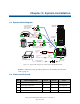
Installing 24 VDC Robot Cable
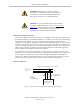
1.
Connect one end of the shielded 24 VDC cable to your user-supplied 24 VDC power
supply. See Figure 3-2. . The cable shield should be connected to frame ground on the
power supply. Do not turn on the 24 VDC power until instructed to do so in .
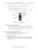
2.
Plug the mating connector end of the 24 VDC cable into the 24 VDC connector on the
interface panel on the back of the robot. The cable shield should be connected to the
ground point on the interface panel.
–
+
24V, 8A
Frame Ground
User-Supplied
Power Supply
24 VDC
Adept Cobra
ePLC600/800 Robot
User-Supplied Shielded
Power Cable
Attach shield from user-
supplied cable to frame
ground on power supply.
Attach shield from user-
supplied cable to ground
screw on Cobra ePLC600/800
Interface Panel.
–
GND
+
Figure 3-2. User-Supplied 24 VDC Cable
Adept Cobra ePLC600/800 Robot, User’s Guide, Rev A
Page 26 of 108