
User`s guide


Adept Cobra ePLC600/800 Robot User’s Guide, Rev A
Page 23 of 108
Chapter 3: System Installation
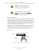
3.1 System Cable Diagram
DC
IN
24 V
GND
AC
200 -
240 V
Ø
1
XBELTIO
XIO
Servo
ENETENET
XSYSTEM
Adept Cobra
ePLC robot
24 VDC, 6 A
Power Supply
200-240 VAC
10 A
single-phase
AC Power
Cable
DC Power
Cable
Front Panel
Cable
Front Panel
User-Supplied PC
running PLC
Programming Software
T20 Adapter
Cable
XMCP Jumper Plug
XMCP
XFP
XUSR
XUSR Jumper Plug
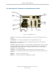
eAIB
XSYSTEM
Cable
Robot Interface
Panel
XUSR for:
- User E-Stop/Safety Gate
- Muted Safety Gate
- Jumper plug required
when not used
Ethernet Cable from
PC to PLC
T20 Bypass Plug
User-Supplied
Ground Wire
T20 Pendant (optional)
Either T20 Pendant,T20 Bypass Plug, or
XMCP Jumper Plug must be used
2
3
4a
A
B
G
H
J
4a
4
4
1
5
6
7
9
8
L
M
Q
P
E
K
D
N
3
85 - 264 VAC
Universal
Input
DC
IN
24V
GND
AC
200 -
240V
Ø
1
XBELTIO
XIO
Servo
ENETENET
XSYSTEM
Ethernet from
PLC to eAIB
FP Jumper Plug
F
Either Front Panel or
FP plug must be used
3a
2a
C
PLC
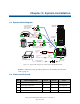
Figure 3-1. System Cable Diagram for Adept Cobra ePLC600/800 robots
NOTE:For additional system grounding information, see Installing 24 VDC Robot
Cable on page 26.
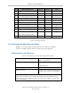
3.2 Cable and Parts List
Part Cable and Parts List Part # Part of: Notes
A eAIB XSYSTEM Cable 13323-000 standard
B User E-Stop, Safety Gate n/a n/a user-supplied
C XUSR Jumper Plug 04736-000 13323-000 standard
D Front Panel 90356-10358 standard