Adept Cobra ePLC600 & ePLC800 Robot User's Guide
Adept Cobra ePLC600 & ePLC800 Robot User's Guide P/N: 13400-000, Rev A May, 2013 5960 Inglewood Drive • Pleasanton, CA 94588 • USA • Phone 925.245.3400 • Fax 925.960.0452 Otto-Hahn-Strasse 23 • 44227 Dortmund • Germany • Phone +49.231.75.89.40 • Fax +49.231.75.89.450 Block 5000 Ang Mo Kio Avenue 5 • #05-12 Techplace II • Singapore 569870 • Phone +65.6755 2258 • Fax +65.
Copyright Notice The information contained herein is the property of Adept Technology, Inc., and shall not be reproduced in whole or in part without prior written approval of Adept Technology, Inc. The information herein is subject to change without notice and should not be construed as a commitment by Adept Technology, Inc. The documentation is periodically reviewed and revised. Adept Technology, Inc., assumes no responsibility for any errors or omissions in the documentation.
Table of Contents Chapter 1: Introduction 1.1 Product Description Adept Cobra ePLC600/ePLC800™ Robots eAIB™ (Amplifiers in Base) 9 9 9 10 1.2 Dangers, Warnings, Cautions, and Notes 11 1.3 Safety Precautions 12 1.4 What to Do in an Emergency Situation 12 1.5 Additional Safety Information 12 Manufacturer’s Declaration of Conformity (MDOC) Adept Robot Safety Guide 12 12 1.6 Intended Use of the Robots 13 1.7 Installation Overview 13 1.8 Manufacturer’s Declaration 14 1.
Table of Contents 3.4 Connecting 200-240 VAC Power to Robot Specifications for AC Power Details for AC Mating Connector Creating the 200-240 VAC Cable Installing AC Power Cable to Robot 3.5 Grounding the Adept Robot System 27 27 29 29 30 30 Grounding the Robot Base Grounding Robot-Mounted Equipment 30 31 3.6 Connecting the PLC to the Robot 31 Installing Adept ACE Software Setting the Robot IP Address Setting the Robot IP Address on the PLC 3.
Table of Contents 5.7 Replacing the eAIB Chassis Removing the eAIB Chassis Installing a New eAIB Chassis 5.8 Commissioning a System with an eAIB Safety Commissioning Utilities E-Stop Configuration Utility E-Stop Verification Utility Teach Restrict Configuration Utility Teach Restrict Verification Utility 5.9 Replacing the Encoder Battery Pack Battery Replacement Time Periods Battery Replacement Procedure Chapter 6: Optional Equipment Installation 58 58 60 61 62 63 64 64 65 66 66 67 69 6.
Table of Contents Cover Removal Procedure Cover Reinstallation Procedure 94 95 8.4 Customer Requirements 96 Sealing the Tool Flange Pressurizing the Robot 8.5 User Connectors User Electrical User Air Lines Robot Solenoid Option 8.6 Maintenance 96 97 97 98 99 99 99 IP-65 Bellows Replacement 8.7 Dimension Drawing for Cable Seal Assembly Chapter 9: Cleanroom Robots Cleanroom Specifications 99 101 103 103 9.1 Connections 104 9.2 Requirements 104 9.3 Exclusions and Incompatibilities 104 9.
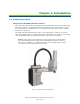
Chapter 1: Introduction 1.1 Product Description Adept Cobra ePLC600/ePLC800™ Robots The Adept Cobra ePLC600 Robot and Adept Cobra ePLC800 Robot are four-axis SCARA robots (Selective Compliance Assembly Robot Arm). See the following two figures. Joints 1, 2, and 4 are rotational; Joint 3 is translational. For a description of the robot joint locations, see Robot Joint Motions on page 10. The Adept Cobra ePLC600/800 robots require a user-supplied PLC for motion control.
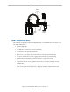
Chapter 1: Introduction Joint 2 Joint 1 Joint 3 Inner Link Outer Link Joint 4 Figure 1-2. Robot Joint Motions eAIB™ (Amplifiers in Base) The amplifiers for the Adept Cobra ePLC600/800 robots are embedded in the base of the robot.
Chapter 1: Introduction Figure 1-3. Amplifier on Robot, ePLC600 Shown 1.2 Dangers, Warnings, Cautions, and Notes There are six levels of special alert notation used in Adept manuals. In descending order of importance, they are: DANGER: This indicates an imminently hazardous electrical situation which, if not avoided, will result in death or serious injury. DANGER: This indicates an imminently hazardous situation which, if not avoided, will result in death or serious injury.
Chapter 1: Introduction NOTE: Notes provide supplementary information, emphasize a point or procedure, or give a tip for easier operation. 1.3 Safety Precautions DANGER: Adept Cobra ePLC600/800 robots can cause serious injury or death, or damage to themselves and other equipment, if the following safety precautions are not observed.
Chapter 1: Introduction 1.6 Intended Use of the Robots The Adept Cobra ePLC600/800 robots are intended for use in parts assembly and material handling for payloads less than 5.5 kg (12.1 lb). See for complete information on the robot specifications. Refer to the Adept Robot Safety Guide for details on the intended use of Adept robots. 1.7 Installation Overview The system installation process is summarized in the following table.
Chapter 1: Introduction 1.8 Manufacturer’s Declaration The Manufacturer’s Declaration of Incorporation and Conformity for Adept robot systems can be found on the Adept website, in the Download Center of the Support section. http://www.adept.com/support/downloads/file-search NOTE: The Download Center requires that you are logged in for access. If you are not logged in, you will be redirected to the Adept website Login page. 1. From the Download Types drop-down list, select Manufacturer Declarations 2.
Chapter 1: Introduction Adept Document Library The Adept Document Library (ADL) contains documentation for Adept products. You can access the ADL from the Adept website. Select: Support > Document Library from the Adept home page. To go directly to the Adept Document Library, type the following URL into your browser: http://www.adept.com/Main/KE/DATA/adept_search.htm To locate information on a specific topic, use the Document Library search engine on the ADL main page.
Chapter 2: Robot Installation 2.1 Transport and Storage This equipment must be shipped and stored in a temperature-controlled environment, within the range –25 C to +55 C. The recommended humidity range is 5 to 90 percent, noncondensing. It should be shipped and stored in the Adept-supplied packaging, which is designed to prevent damage from normal shock and vibration. You should protect the package from excessive shock and vibration.
Chapter 2: Robot Installation Before signing the carrier’s delivery sheet, please compare the actual items received (not just the packing slip) with your equipment purchase order and verify that all items are present and that the shipment is correct and free of visible damage. l If the items received do not match the packing slip, or are damaged, do not sign the receipt. Contact Adept as soon as possible. l If the items received do not match your order, please contact Adept immediately.
Chapter 2: Robot Installation 2.5 Mounting the Robot WARNING: Only qualified service personnel may install or service the robot system. Mounting Surface The Adept Cobra ePLC600/800 robots are designed to be mounted on a smooth, flat, level tabletop. The mounting structure must be rigid enough to prevent vibration and flexing during robot operation. Adept recommends a 25 mm (1 in.) thick steel plate mounted to a rigid tube frame. Excessive vibration or mounting flexure will degrade robot performance.
Chapter 2: Robot Installation Robot Mounting Procedure 1. Using the dimensions shown in the previous figure, drill and tap the mounting surface for four M12 - 1.75 x 36 mm (or 7/16 - 14 UNC x 1.50 in.) machine bolts. Bolts are usersupplied. 2. While the robot is still bolted to the transportation pallet, connect the hydraulic lift to the eyebolt at the top of the inner link (see Chapter 2). Take up any slack, but do not lift the robot at this time.
Chapter 2: Robot Installation 2.6 Description of Connectors on Robot Interface Panel Figure 2-3. eAIB Interface Panel 24 VDC—for connecting user-supplied 24 VDC power to the robot. The mating connector is provided. Ground Point—for connecting cable shield from user-supplied 24 VDC cable. 200/240 VAC—for connecting 200-240 VAC, single-phase, input power to the robot. The mating connector is provided. XIO (DB26, high density, female) — for user I/O signals for peripheral devices.
Chapter 3: System Installation 3.
Chapter 3: System Installation Part Cable and Parts List Part # Part of: Notes E Front Panel Cable 10356-10500 90356-10358 standard F Front Panel Jumper Plug 25165-30154 13323-000 standard G XMCP Bypass Jumper Plug 04737-000 13323-000 standard H T20 Bypass Plug 10048-000 10055-000 standard with T20 J T20 Adapter Cable 10051-003 10055-000 standard with T20 K T20 (optional) 10055-000 L AC Power Cable (option) 04118-000 04972-000 user-supplied M 24 VDC Power Cable (option)
Chapter 3: System Installation NOTE: Fuse information is located on the eAIB electronics. The power requirements for the user-supplied power supply will vary depending on the configuration of the robot and connected devices. Adept recommends a 24 V, 6 A power supply to allow for startup current draw and load from connected user devices, such as solenoids and digital I/O loads. If multiple robots are sharing a 24 V power supply, increase the supply capacity by 3 A for each additional robot.
Chapter 3: System Installation Recommended crimping tool, Molex Hand Crimpers Molex P/N 63811-0400 Digi-Key P/N WM9907-ND NOTE: The 24 VDC cable is not supplied with the system, but is available in the optional Power Cable kit. See Table 3-1. Procedure for Creating 24 VDC Cable 1. Locate the connector and pins shown in Table 3-4. 2. Use 14-16 AWG wire to create the 24 VDC cable. Select the wire length to safely reach from the user-supplied 24 VDC power supply to the robot base. 3.
Chapter 3: System Installation NOTE: In order to maintain compliance with standards, Adept recommends that DC power be delivered over a shielded cable, with the shield connected to frame ground at both ends of the cable. 3.4 Connecting 200-240 VAC Power to Robot WARNING: Appropriately sized Branch Circuit Protection and Lockout / Tagout Capability must be provided in accordance with the National Electrical Code and any local codes.
Chapter 3: System Installation WARNING: Adept systems require an isolating transformer for connection to mains systems that are asymmetrical or use an isolated (impedant) neutral. Many parts of Europe use an impedant neutral. DANGER: AC power installation must be performed by a skilled and instructed person—refer to the Adept Robot Safety Guide. During installation, unauthorized third parties must be prevented from turning on power through the use of fail-safe lockout measures.
Chapter 3: System Installation Note: F4 and F5 are user-supplied, must be slow-blow. L1 3Ø 200–240 VAC L2 L3 F5 10 A 200–240 VAC F4 10 A E User-Supplied AC Power Cable E L = Line 1 N = Line 2 E = Earth Ground N L Adept Cobra ePLC600/800 Robots 1Ø 200–240 VAC Figure 3-4. Single-Phase Load across L1 and L2 of a Three-Phase Supply NOTE: If a three-phase power source is used, it must be symmetrically-earthed (with grounded neutral).
Chapter 3: System Installation 6. Insert the wires into the connector through the removable bushing. 7. Connect each wire to the correct terminal screw, and tighten the screw firmly. 8. Tighten the screws on the cable clamp. 9. Reinstall the cover and tighten the screw to seal the connector. 10. Prepare the opposite end of the cable for connection to the facility AC power source. Figure 3-5. AC Power Mating Connector Installing AC Power Cable to Robot 1.
Chapter 3: System Installation Figure 3-6. Ground Point on Robot Base Grounding Robot-Mounted Equipment The following parts of Adept Cobra ePLC600/800 robots are not grounded to protective earth: the Joint 3 quill and the tool flange. If hazardous voltages are present at any user-supplied robot-mounted equipment or tooling, you must install a ground connection from that equipment/tooling to the ground point on the robot base. Hazardous voltages can be considered anything in excess of 30 VAC (42.
Chapter 3: System Installation .NET, and installs it automatically if it is not already installed. The Adept ACE software needs to be v. 3.4 or later for the connection to a PLC. 1. Insert the CD-ROM into the CD-ROM drive of your PC. If Autoplay is enabled, the Adept software CD-ROM menu is displayed. If Autoplay is disabled, you will need to manually start the CD-ROM.
Chapter 3: System Installation Figure 3-7. Detect and Configure Button, Circled The IP address detection and configuration window will open. See the following figure.
Chapter 3: System Installation Figure 3-8. Detection and Configuration Window 4. Power-cycle the ePLC Cobra. Wait for it to reboot. The ACE software will show the IP address of any controllers it detects.
Chapter 3: System Installation Figure 3-9. IP Addresses Detected 5. You can change the IP address and subnet mask in the Desired Address and Desired Subnet fields, if needed. 6. Click OK. The ACE software will ask you to wait for the controller to reboot. See the following figure.
Chapter 3: System Installation Figure 3-10. Waiting for Controller to Reboot Setting the Robot IP Address on the PLC Using your PLC software, set the IP address for the PLC to connect to on the robot. The following figure is an example of an Allen Bradley PLC, with RS Logix software. Figure 3-11.
Chapter 3: System Installation The PLC should now be able to communicate with the robot. 3.7 Installing User-Supplied Safety Equipment The user is responsible for installing safety barriers to protect personnel from coming in contact with the robot unintentionally. Depending on the design of the workcell, safety gates, light curtains, and emergency stop devices can be used to create a safe environment. Read the Adept Robot Safety Guide for a discussion of safety issues.
Chapter 4: System Operation 4.1 Robot Status LED Description The robot Status LED indicator is located on the top of the robot. The blinking pattern indicates the status of the robot. The Adept Cobra ePLC robots support the UL standard. The LED on these robots is amber. See the following figure and table. Figure 4-1. Robot Status LED Indicator Location Table 4-1.
Chapter 4: System Operation The displayed fault code will continue to be displayed even after the fault is corrected or additional faults are recorded. All displayed faults will be cleared from the display, and reset to a no-fault condition, upon successfully enabling high power to the robot, or power cycling the 24 V supply to the robot. Figure 4-2. Status Panel Table 4-2.
Chapter 4: System Operation For more information on status codes, go to the Adept Document Library on the Adept website, and in the Procedures, FAQs, and Troubleshooting section, look for the Adept Status Code Summary document. 4.3 Brakes The robot has a braking system that decelerates the robot in an emergency condition, such as when the emergency stop circuit is open or a robot joint passes its softstop.
Chapter 4: System Operation 1. XFP connector Connects to the XFP connector on the XSYSTEM cable. 2. System 5 V Power-On LED Indicates whether or not power is connected to the robot. 3. Manual/Automatic Mode Switch Switches between Manual and Automatic mode. In Automatic mode, executing programs control the robot, and the robot can run at full speed. In Manual mode, the system limits robot speed and torque so that an operator can safely work in the cell.
Chapter 4: System Operation Cobra ePLC600/ePLC800 Robot XIO Connector 12 Input signals: 1001 to 1012 8 Output signals: 1 to 8 Figure 4-4. Connecting Digital I/O to the System Table 4-4. Default Digital I/O Signal Configuration, Single Robot System Location Type Signal Range Robot 1 XIO connector Inputs 1001–1012 Outputs 0001–0008 Using Digital I/O on Robot XIO Connector The XIO connector on the robot interface panel offers access to digital I/O, 12 inputs and 8 outputs.
Chapter 4: System Operation Pin No. Designation Signal Bank Signal Number 7 Input 4.1 1 1004 8 Input 5.1 1 1005 9 Input 6.1 1 1006 10 GND 11 24 VDC 12 Common 2 2 13 Input 1.2 2 1007 14 Input 2.2 2 1008 15 Input 3.2 2 1009 16 Input 4.2 2 1010 17 Input 5.2 2 1011 18 Input 6.
Chapter 4: System Operation XIO Input Signals The 12 input channels are arranged in two banks of six. Each bank is electrically isolated from the other bank and is optically isolated from the robot’s ground. The six inputs within each bank share a common source/sink line. The inputs are accessed through direct connection to the XIO connector (see the previous table), or through the optional XIO Termination Block. See the documentation supplied with the termination block for details.
Chapter 4: System Operation Typical Input Wiring Example Adept-Supplied Equipment User-Supplied Equipment Wiring Terminal Block (equivalent circuit) Signal 1001 Signal 1002 Input Bank 1 Signal 1005 Signal 1006 4 Part Present Sensor 5 Feeder Empty Sensor 6 Part Jammed Sensor 7 Sealant Ready Sensor 8 9 Bank 1 3 Common 2 +24V GND 1 Signal 1007 Signal 1008 Input Bank 2 Signal 1009 Signal 1010 Signal 1011 Signal 1012 13 14 15 16 17 18 Bank 2 12 Common 10 GND +24V Bank 2 configured for Sourc
Chapter 4: System Operation XIO Output Specifications Table 4-7. XIO Output Circuit Specifications Parameter Value Power supply voltage range See Specifications for 24 VDC Power on page 24. Operational current range, per channel I Total Current Limitation, all channels on. I ≤ 1.0 A @ 50° C ambient I ≤ 1.5 A @ 25° C ambient out ≤ 700 mA total total ON state resistance (I out = 0.5 A) R on ≤ 0.32 Ω @ 85° C ≤ 25 µA Output leakage current I Turn on response time 125 µsec max.
Chapter 4: System Operation Typical Output Wiring Example Figure 4-6. Typical User Wiring for XIO Output Signals XIO Breakout Cable The XIO Breakout cable is available as an option—see the following figure. This cable connects to the XIO connector on the eAIB, and provides flying leads on the user’s end, for connecting input and output signals in the workcell. The cable length is 5 M (16.4 ft). For the wire chart on the cable, see the following table.
Chapter 4: System Operation Table 4-8. XIO Breakout Cable Wire Chart Signal Designation Pin No. Wire Color 1 GND White 2 24 VDC White/Black 3 Common 1 Red 4 Input 1.1 Red/Black 5 Input 2.1 Yellow 6 Input 3.1 Yellow/Black 7 Input 4.1 Green 8 Input 5.1 Green/Black 9 Input 6.1 Blue 10 GND Blue/White 11 24 VDC Brown 12 Common 2 Brown/White 13 Input 1.2 Orange 14 Input 2.2 Orange/Black 15 Input 3.2 Gray 16 Input 4.2 Gray/Black 17 Input 5.
Chapter 4: System Operation 4.6 Starting the System for the First Time Follow the steps in this section to safely bring up your robot system.
Chapter 4: System Operation 3. Turn on the 24 VDC power to the robot. l The Status Panel displays OK. l The Robot Status LED will be off. 4. Verify the Auto/Manual switch on the Front Panel is set to Auto Mode. 5. Switch on the PLC. The Adept web site has some examples for the Allen Bradley PLC using RS Logix: http://www.adept.com/index.php?option=com_ content&view=article&id=367&Itemid=484&dir=JSROOT%2FDownloadLibrary/ePLC-Examples This gives some examples to start with.
Chapter 4: System Operation Once high power is enabled, the Robot Status Panel displays ON, and the Robot Status LED will be lit. Verifying E-Stop Functions Verify that all E-Stop devices are functional (pendant, Front Panel, and user-supplied). Test each mushroom button, safety gate, light curtain, etc., by enabling high power and then opening the safety device. The High Power push button/light on the Front Panel should go out for each.
Chapter 5: Maintenance 5.1 Field-replaceable Parts WARNING: Only qualified service personnel may install or service the robot system. The following parts are the only field-replaceable parts: Table 5-1. Field-replaceable Parts Part Adept Part Number Encoder battery 09977-000 (3.6 V, 6.8 Ah) (This has replaced part number 02704-000) eAIB (Amp-In-Base) 11472-000 These parts must only be replaced with the Adept part numbers in the preceding table. 5.
Chapter 5: Maintenance NOTE: The frequency of these procedures will depend on the particular system, its operating environment, and amount of usage. Use the times in this table as guidelines and modify the schedule as needed. WARNING: Lockout and tagout power before servicing. WARNING: The procedures and replacement of parts mentioned in this section should be performed only by skilled or instructed persons, as defined in the Adept Robot Safety Guide.
Chapter 5: Maintenance 5.5 Checking Robot for Oil around Harmonic Drive The Adept Cobra ePLC600 and ePLC800 robots use oil in the harmonic drive components for lubrication. Periodically inspect the robot for any signs of oil in areas immediately outside of the harmonic drive. Check these locations: l the area around Joint 1 l the area around Joint 2 l inside the base of the robot, by opening the eAIB chassis and inspecting internally.
Chapter 5: Maintenance For the Cleanroom version, refer to for instructions on removing the bellows. The outer link cover is standard. 3. Switch on 24 VDC power to the robot. 4. Press the brake button and move Joint 3 to the top of its travel. Remove any existing grease with a clean, lint-free, soft cloth. 5. Using a syringe, apply a small bead of grease to the Joint 3 ball screw grooves, see Figure 5-1. Apply grease to the three vertical grooves and the spiral groove. 6.
Chapter 5: Maintenance Joint 3 Ball Screw Lubrication Points A A A Joint 3 Ball Screw Lubrication Points A Lower Quill Grease Locations Upper Quill Grease Locations Quill Shaft Vertical Groove Lube Point A Vertical Groove Lube Point B Top View Looking Down NOTE: Apply grease to the three vertical grooves Vertical Groove Lube Point C and the spiral groove Section A-A Figure 5-1.
Chapter 5: Maintenance 5.7 Replacing the eAIB Chassis CAUTION: Follow appropriate ESD procedures during the removal/replacement phases. Removing the eAIB Chassis 1. Switch off the 24 VDC input supply to the chassis. 2. Switch off the 200/240 VAC input supply to the chassis. Lock out and tag out power. 3. Disconnect the 24 VDC supply cable from the chassis +24 VDC input connector. 4. Disconnect the 200/240 VAC supply cable from the chassis AC Input connector. 5.
Chapter 5: Maintenance Figure 5-3. Opening and Removing Chassis 9. Disconnect the “white” amplifier cable from the amplifier connector located on the chassis bracket. See the following figure. Figure 5-4. Connectors on Chassis and ePMAI Board 10. Carefully disconnect the INT1, INT2, ENC1, and ENC2 cables from their connectors on the ePMAI board, by disengaging the securing latches: 11. Using a 5 mm hex wrench, disconnect and remove the ground wire from the chassis. Keep the screw for reassembly later.
Chapter 5: Maintenance Figure 5-5. Ground Screw Hole on eAIB Chassis 12. Carefully remove the chassis from the robot, and place it aside. Tag it with the appropriate fault diagnosis faults/errors and robot serial number information. Installing a New eAIB Chassis 1. Carefully remove the new chassis from its packaging, check it for any signs of damage, and remove any foreign packing materials or debris from inside the chassis. 2. Carefully place the chassis next to the robot. 3.
Chapter 5: Maintenance Figure 5-6. Installing eAIB Chassis in Robot Base 6. Carefully insert the chassis into the robot base in the groove at the bottom of the base— see Figure 5-6. Tilt the chassis up and into place against the robot, making sure that none of the cables get trapped or pinched and that the chassis O-ring is not damaged during installation. 7. Once the chassis is in place, use a 5 mm hex wrench to tighten the chassis securing screw. See Figure 5-2 for details. 8.
Chapter 5: Maintenance l If the system will not power up, and the robot status display shows SE, you need to commission the system. l If the system will not power up in Manual mode, and the robot status display shows TR, you need to commission the system. Safety Commissioning Utilities The Adept eAIB adds two functions that implement safety in hardware: l E-Stop This serves as a backup to the standard software E-Stop process.
Chapter 5: Maintenance Figure 5-7. Adept Front Panel l No E-Stops can be activated. l For Configuration (E-Stop and Teach Restrict), the eAIB Commissioning Jumper must be plugged into the XBELTIO jack on the eAIB. NOTE: This is the only time that this jumper will be used. It is part number 11901-000, and must be removed for Verification and normal operation. Figure 5-8. eAIB Commissioning Jumper l An Adept pendant is required for the Teach Restrict verification.
Chapter 5: Maintenance Procedure From within the Adept ACE software: 1. Open the robot object editor. 2. Select Configure > Safety Settings > Configure ESTOP Hardware Delay, then click Next. This procedure will configure Channel A and then Channel B. It will then report the delay that it set for each. 3. Reboot the robot controller. 4. Reboot the eAIB. E-Stop Verification Utility This utility verifies that the hardware E-Stop parameters are set correctly and that the hardware E-Stop is working.
Chapter 5: Maintenance 1. Open the robot object editor. 2. Select Configure > Safety Settings > Configure Teach Restrict, then click Next. 3. From the Prerequisite screen, click Next. The wizard will go through all of the robot's motors, and display messages that it is configuring Channel A and B for each. It will then record the configuration, and display the target times that it set. 4. Click Finish. 5. Reboot the robot controller.
Chapter 5: Maintenance The robot will move each joint, in succession. It will generate an over-speed condition for each, and verify that the hardware detected the over-speed condition. 4. Click Next, to proceed to the Manual Mode Procedure. If the Automatic Mode Procedure fails, you will not be allowed to proceed with the Manual Mode. Manual Mode Procedure The manual mode of this verification requires the use of an Adept pendant. For this verification, the Front Panel keyswitch must be in Manual mode. 1.
Chapter 5: Maintenance NOTE: Dispose of the battery according to all local and national environmental regulations regarding electronic components. Battery Replacement Procedure 1. Obtain the replacement battery pack. 2. Switch off the 24 VDC input supply to the robot. 3. Switch off the 200/240 VAC input supply to the robot. 4. Disconnect the 24 VDC supply cable from the robot +24 VDC input connector. For the connector location, see System Cable Diagram on page 23. 5.
Chapter 5: Maintenance NOTE: Dispose of the battery pack in accordance with all local and national environmental regulations regarding electronic components. 12. Place the new battery pack in the original location on the base of the robot. 13. Close the robot by reversing the steps in the beginning of this procedure. 14. Reconnect the 200/240 VAC supply cable to the robot AC input connector. 15. Reconnect the 24 VDC supply cable to the robot +24 VDC input connector.
Chapter 6: Optional Equipment Installation 6.1 Installing End-Effectors The user is responsible for providing and installing any end-effector or other end-of-arm tooling. End-effectors can be attached to the tool flange using four M6 screws. See Tool Flange Dimensions for Both Robots on page 85 for a detailed dimension drawing of the tool flange.
Chapter 6: Optional Equipment Installation Quill shaft M4 Socket-head cap screws Tool flange assembly Setscrew Figure 6-1. Tool Flange Removal Details Installing the Flange 1. Make sure the steel ball is in the setscrew hole inside the flange. Hold it in place with your finger as you get ready to install the flange. 2. Slide the flange up on the quill shaft as far as it will go, and rotate until the setscrew is lined up with the original vertical groove. 3. Support the flange while using a 2.
Chapter 6: Optional Equipment Installation Figure 6-2. User Connectors on Joint 1 Figure 6-3. User Connectors on Joint 2 User Electrical Lines NOTE: DeviceNet and IO Blox are not supported on the ePLC family of Cobra robots. There is a 25-pin male connector (24 conductor) on the robot user panel on the back of Joint 1 for user electrical lines, see Figure 6-2. This connector is wired directly to a 25-pin female connector on the top of the outer link, see Figure 6-3.
Chapter 6: Optional Equipment Installation Figure 6-4. Internal User Connectors—OP3/4, EOAPWR, ESTOP WARNING: When the Outer link cover is removed, you see the label shown above. Do not remove the J3-ENC or J4-ENC encoder cable connectors from their sockets. If they are removed, the calibration data will be lost and the robot must be run through a factory recalibration process, which requires special software and tools. Figure 6-5.
Chapter 6: Optional Equipment Installation SOLND Connector This 4-pin connector provides the output signals for the optional Robot Solenoid Kit. See the previous figure and following table. For installation details, see Installing the Robot Solenoid Kit on page 77. Table 6-1.
Chapter 6: Optional Equipment Installation SOLND Connector Circuit +24 VDC Signal 3001 (equivalent circuit) GND Signal 3002 For optional Robot Solenoid Kit installation, or other user supplied devices. Pin 1 Load Pin 2 Pin 3 Load Pin 4 GND OP3/4 Connector Circuit +24 VDC Signal 3003 (equivalent circuit) GND Signal 3004 For optional second set of solenoids, or other user supplied devices. Pin 1 Load Pin 2 Pin 3 Load Pin 4 GND Figure 6-6.
Chapter 6: Optional Equipment Installation Table 6-4. Internal User Connector Output Circuit Specifications Parameter Value Power supply voltage range 24 VDC ± 10% See Specifications for 24 VDC Power on page 24. Operational current range, per channel I Total Current Limitation, all channels ona I ≤ 1.0 A @ 50° C ambient I ≤ 1.5 A @ 25° C ambient out ≤ 700 mA total total On-state resistance (I out = 0.5 A) R on ≤ 0.
Chapter 6: Optional Equipment Installation Table 6-5. ESTOP Connector Pin # Description 1 ESTOP_INPUT 2 24 V Pin Location ESTOP Connector as viewed on robot Mating Connector: AMP/Tyco #172165-1, 2-pin Mini-Universal Mate-N-Lock AMP/Tyco #770985-1, Pin Contact, Mini-Univ. Mate-N-Lok Typical ESTOP Connector Circuit Pin 1 Pin 2 User-supplied normally-closed contact. Can be connected to a break-away sensor to cause an E-Stop condition when circuit is open.
Chapter 6: Optional Equipment Installation NOTE: The cover on the outer link must be removed for maintenance (lubrication), so keep this in mind when mounting any external equipment to the outer link cover. 6.6 Installing the Robot Solenoid Kit This procedure describes how to mount the 24 V Robot Solenoid option on Adept Cobra ePLC600 and ePLC800 robots. The kit is available as Adept P/N 02853-000. The robot has been pre-wired to accommodate a bank of two 24 VDC solenoid valves.
Chapter 6: Optional Equipment Installation Figure 6-8. Solenoid Mounting Bracket With Connector and Spare Air Line 4. Cut and discard the cable ties holding the spare air line at the top of the mounting bracket. Move the air line away to facilitate the mounting of the solenoid manifold. See Figure 6-8. 5. Mount the solenoid manifold onto the bracket using the supplied M3 x 25 mm screws and washers. See Figure 6-9. 6. Insert the spare air line into the air intake coupling of the solenoid manifold.
Chapter 6: Optional Equipment Installation Figure 6-9. Solenoid Placement Using Mounting Hardware 9. Install the appropriate lengths of 5/32 inch plastic tubing (supplied) into the two output ports on the manifold. l Route the tubing up along the tower bracket next to the quill and down through the center of the quill. l Use cable ties as needed to secure the tubing. 10. Loosen the securing screw on the eAIB chassis, and lower the chassis down flat. See for the location of the securing screw. 11.
Chapter 6: Optional Equipment Installation Figure 6-10. Removing the Cable Strap Plate 12. Remove the four screws for the Joint 1 cover and lift the cover up so you have access to the tubing under the cover. See Figure 6-11. Figure 6-11. Connecting Spare Air Line to User Connector 13. Disconnect the tubing from the 6 mm User Air fitting shown in Figure 6-11. Fold the tubing out of the way and restrain using tie-wraps. 14.
Chapter 6: Optional Equipment Installation NOTE: This 6 mm User Air connector and the 6 mm User Air connector at the top of Figure 6-2 are not available for other uses after this modification. 16. Reinstall the Joint 1 cover, taking care to ensure that all tubing is inside the cover and nothing gets crimped or pinched while pushing the cover into position. Reinstall four screws to secure the cover. Tighten the screws to 1.6 N·m (14 in-lb) of torque. 17.
Chapter 7: Technical Specifications 7.1 Dimension Drawings 417 183 200 Required clearance to open eAIB Chassis 934 888 46 37 387 342 177 31 Required cable clearance 600 325 0 234 0 Figure 7-1.
Chapter 7: Technical Specifications 417 183 200 Required clearance to open eAIB Chassis 918 894 46 37 398 342 31 Required cable clearance 188 800 425 0 234 0 Figure 7-2.
Chapter 7: Technical Specifications 12.0 mm (0.47 in.) See Detail A 20.0 mm (0.79 in.) 3.0 mm (0.12 in.) 43 mm (1.69 in.) ∅ 41.15 mm +.03 mm –.00 mm 45° -A- (∅ 1.620 in.) (+.001 in.) (–.000 in.) Dowel Pin Hole ∅ 6.0 mm +.01 mm – 0 mm ∅ 63.0 mm (2.48 in.) (0.2362 in.) (+.0005 in.) (– 0 in.) -CBC 30° ∅ 50.0 mm (1.9685 in.) 4X M6 x 1- 6H Thru User Ground R 3.56mm (R 0.140in) 5.08mm (0.20in) M3 X 0.5-6H Thru ∅.10 mm (.004 in.) M A M B C M Units in mm 4.14 mm (0.163 in.) 1.5 mm (0.059 in.) 6.
Chapter 7: Technical Specifications 25 4X M4x0.7 - 6H 105 6 Inner Link External Mounting Locations 60 4X M4x0.7 - 6H Units in mm Outer Link External Mounting Locations 105 Figure 7-4. External Tooling on Top of Robot Arm 76 - Cobra ePLC600 135 - Cobra ePLC800 34 90 4X M4x0.7-6H Outer Link - Bottom View 8 Units in mm Figure 7-5.
Chapter 7: Technical Specifications Figure 7-6. Adept Cobra ePLC600 Robot Working Envelope Maximum Intrusion Contact Radius 847.3 mm (33.36 in.) Maximum Radial Reach Functional Area 800 mm (31.50 in.) Minimum Radial Reach 163.6 mm (6.44 in.) 105˚ 105˚ 157.5˚ 157.5˚ Cartesian Limits 300 mm (11.8 in.) Figure 7-7.
Chapter 7: Technical Specifications 7.2 Robot Specifications Description ePLC600 Robot ePLC800 Robot Reach 600 mm (23.6 in) 800 mm (31.5 in) Payload—rated 2.0 kg (4.4 lb) 2.0 kg (4.4 lb) Payload—maximum 5.5 kg (12.1 lb) 5.5 kg (12.
Chapter 7: Technical Specifications Description ePLC600 Robot ePLC800 Robot Joint 1 386°/sec 386°/sec Joint 2 720°/sec 720°/sec Joint 3 1,100 mm/sec (43 in/sec) 1,100 mm/sec (43 in/sec) Joint 4 1200°/sec 1200°/sec Encoder type Absolute Robot Brakes Joints 1, 2, and 4: Dynamic Joint 3: Electric Airline pass-through (quantity) 6 mm diameter (2), 4 mm diameter (3) Electrical pass-through 24 conductors (12 twisted pair) Weight (without options) aSpecifications subject 41 kg (90 lb) 43
Chapter 8: IP-65 Option 8.1 Adept Cobra ePLC800 Robot IP-65 Classification The factory installed IP-65 option kit provides an improved level of dust and water protection. IP-65 means “dust-tight and protection against water jetting.” l Dust Resistance—protection of the equipment inside the robot shell against ingress of solid foreign objects l Specifically for IP-65 Dust Protection—“No ingress of dust is allowed.
Chapter 8: IP-65 Option Cable Seal Housing Figure 8-2. Cable Seal Parts Installation Procedure 1. Disassemble the cable seal assembly into separate pieces by removing all screws. 2. Install the cable seal housing on the back of the robot using four M4x50 screws, four M4 lock washers, and four M4 flat washers. Note that the centered M6 threaded hole must be at the top. See the following figure. Figure 8-3. Cable Seal Housing Installed 3. Attach all system cables to the robot.
Chapter 8: IP-65 Option c. Finally push down on the flange to secure it against the housing. See Figure 8-5 for the lower flange in the installed position. Figure 8-4. Installing Lower Flange Figure 8-5. Lower Flange in Position 5. Seat all of the cables by pushing down into the foam on the lower flange. 6. Attach the upper flange to the lower flange using two M6 x 20 screws, two M6 lock washers, and two M6 flat washers.
Chapter 8: IP-65 Option 8. Install the splash guard using two M6 x 20 screws, two M6 lock washers, and two M6 flat washers. See Figure 8-7. 8.3 Robot Outer Link Cover Removal and Reinstallation The robot outer link cover has special sealing hardware to ensure nothing can enter the inside of the robot. If you need to remove the outer link cover from the robot for any reason, follow the procedures below. Cover Removal Procedure 1. Turn off main power to the power chassis. Lock out and tag out power. 2.
Chapter 8: IP-65 Option 7. When all 8 screws are loose (but not removed), lift the cover up and slide it back along the cable track and out of the way. Protect the cover with a soft cloth or other padding material so the cover does not get scratched. See Figure 8-9. Figure 8-9. IP-65 Robot with Outer Link Cover Removed Cover Reinstallation Procedure 1. Check the cover O-ring around the inner groove of the cover to make sure it is in place and not crimped when installing cover. 2.
Chapter 8: IP-65 Option 8. Remember to turn on the compressed air supply to the system before restarting the robot. 8.4 Customer Requirements The IP-65 robot provides most of the hardware needed to achieve an IP-65 protection level, but customers must provide a way of sealing the tool flange and pressurizing the robot through the compressed air attachment fitting (located at the top of the robot).
Chapter 8: IP-65 Option Pressurizing the Robot The user must supply compressed air to keep a positive airflow pressure in the robot cavity. 1. Remove the red shipping plug from the compressed air fitting on the top of the robot. See the following figure. Figure 8-11. Compressed Air Fitting on Robot 2. Connect a compressed air source to the air fitting. The specification for the regulated air supply is shown in the following table. Table 8-1.
Chapter 8: IP-65 Option User Electrical On the back of the Joint 1 cover, the user electrical connector is filled with a removable plug at the factory. See the following figure. If you use this connector, you must provide a seal (see note below) at the connection to prevent moisture from entering the robot. NOTE: The user electrical connector (DB-25) on the back of the Joint 1 cover requires a gel seal gasket to maintain an adequate seal. The gasket is supplied in the accessory kit. Figure 8-12.
Chapter 8: IP-65 Option User Air Lines On the back of the Joint 1 cover, the user air line connectors are fitted with removable plugs at the factory. See Figure 8-12. The user air line connectors on the outer link are accessible with the cover removed. See Figure 8-13 for locations of the internal connectors. When routing air lines outside of the robot, any fittings you use must maintain an adequate seal in the cover to prevent moisture from entering the outer link.
Chapter 8: IP-65 Option NOTE: Align the bellows clamps with the bellows seam, on both upper and lower clamps. Bellows Seam Bellows Clamp Bellows Clamp Bellows Cross-section View Figure 8-14. Bellows Replacement Figure 8-15.
Chapter 8: IP-65 Option 8.7 Dimension Drawing for Cable Seal Assembly 432 208 Required clearance to open eAIB controller with the IP-65 connector Cable sealing box on IP-65 version only 74 308 Figure 8-16.
Chapter 9: Cleanroom Robots The Adept Cobra ePLC robots are available in Class 10 Cleanroom models. NOTE: Class 1 Limits can be achieved by maintaining the robot speed at Speed 50 or below. This option is a factory-installed configuration. Changes to the robot include the addition of a bellows assembly mounted at the Joint 3 quill, fully sealed access covers, and a two-stage vacuum system to evacuate the arm.
Chapter 9: Cleanroom Robots 9.1 Connections Figure 9-2. Cleanroom Connections 9.2 Requirements Table 9-2. Cleanroom Robot Requirements Vacuum source 0.80 m 3/min (28 ft3/min) minimum volumetric flow rate 6 mm of water (0.2 inches of water) differential pressure measured between the robot and the vacuum source 3/4 inch NPT female thread pipe fitting at the back of the robot Compressed air source Clean, dry, oil-free compressed air 75 psi (0.52 MPa) 1.4 SCFM (.04 m 3/min.
Chapter 9: Cleanroom Robots 9.4 Cleanroom Maintenance Bellows Replacement Check the bellows periodically for cracks, wear, or damage. Replace bellows (Adept P/N 04625000) if necessary, using the procedure below. 1. Remove the lower bellows clamp ring from the bearing ring by loosening the screw on the clamp. See Figure 9-3. 2. Remove the tool flange. For the tool flange removal procedure, refer to Removing and Installing the Tool Flange on page 69. 3.
P/N: 13400-000, Rev A 5960 Inglew ood D rive Pleas anton, C A 94588 925 · 245 · 3400