
User`s guide


Chapter 4 - System Installation
56 Adept Quattro s650H Robot User’s Guide, Rev A
NOTE: A separate 24 VDC cable is required for the SmartController. That
cable uses a different style of connector. See the Adept SmartController
User’s Guide.
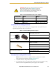
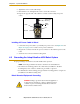
3. Crimp the pins onto the wires using the crimping tool.
4. Insert the pins into the connector. Confirm that the 24 VDC and ground wires are
in the correct terminals in the plug.
5. Prepare the opposite end of the cable for connection to your user-supplied
24 VDC power supply.
Installing 24 VDC Robot Cable
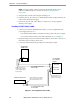
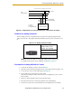
1. Connect one end of the shielded 24 VDC cable to your user-supplied 24 VDC
power supply. See Figure 4-3.
• The cable shield should be connected to frame ground on the power supply.
• Do not turn on the 24 VDC power until instructed to do so in Chapter 5.
2. Plug the mating connector end of the 24 VDC cable into the 24 VDC connector on
the interface panel on the top of the robot.
3. Connect the cable shield to the ground point on the interface panel.
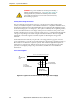
Figure 4-3. User-Supplied 24 VDC Cable
–
+
24 V, 6 A
Frame Ground
24 V, 5 A
–
+
User-Supplied
Power Supply
24 VDC
Adept Quattro
s650H Robot
User-Supplied Shielded
Power Cable
-
+
Adept SmartController
User-Supplied Shielded
Power Cable
Attach shield from user-supplied
cable to side of controller using
star washer and M3 x 6 screw.
Attach shield from user-
supplied cables to frame
ground on power supply.
Attach shield from user-
supplied cable to ground
screw on Quattro s650H
Interface Panel.
–
GND
+