
User`s guide


Description of Connectors on Robot Interface Panel
Adept Quattro s650H Robot User’s Guide, Rev A 53
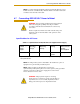
4.4 Description of Connectors on Robot Interface Panel
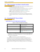
Figure 4-2. Robot Interface Panel
Connector Connects to Notes
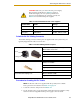
24 VDC 24 VDC to the robot User-supplied
Ground Point Cable shield from 24 VDC cable User-supplied
200/240 VAC 200-240 VAC, single-phase, input
power to the robot
Mating connector is provided.
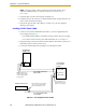
XSLV XSYS cable from the controller
XSYS connector
Supplied DB-9
SmartServo
1 & 2
IEEE 1394 cable from the
controller (SmartServo 1.1 or 1.2)
to the robot (SmartServo 1)
SmartServo 2 can be used to
connect to a second robot or
another 1394-based motion axis.
RS-232 Not used with Quattro robots
XPANEL Not used with Quattro robots
XIO User I/O signals for peripheral
devices
This connector provides 8
outputs and 12 inputs. See 5.5 on
page 67 for connector pin
allocations for inputs and outputs.
That section also contains details
on how to access these I/O
signals via V+. (DB26, high
density, female)
24 VDC
Input
200-240 VAC
XSLV
XIO
XPANEL
RS-232
SmartServo Port 1
+24 VDC
Pin
Ground
Point
SmartServo Port 2