
User`s guide


Adept Quattro s650H Robot User’s Guide, Rev A 51
System Installation 4
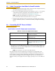
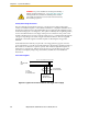
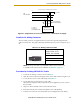
4.1 System Cable Diagram
Figure 4-1. System Cable Diagram
NOTE: See “Installing 24 VDC Robot Cable” on page 56 for additional
information on system grounding.
GND
XSLV
1
2
SmartServo
RS-232
XPANEL
AC INPUT
(200-240 VAC 1&)
+24V
DC INPUT
(24 VDC)
XIO
Ethernet to PC
IEEE 1394 Cable
Controller SmartServo (Port 1.1) to
Robot SmartServo (Port 1)
Adept
SmartController
Adept Quattro
s650H Robot AIB
User-Supplied
24 VDC Power
Supply
User-Supplied
200-240 VAC,
single-phase
Controller (XFP) to
Front Panel (XFP)
Front Panel
XSYS Cable
Controller (XSYS) to
Robot (XSLV)
24 VDC Power to
Controller (XDC1)
24 VDC Power
to Robot
(+24 VDC Input)
Controller (XMCP) to
Pendant
User-Supplied Desktop
or Laptop PC running the
Adept software environment
Terminator
Installed
User-Supplied Ground Wire
User-Supplied
Ground Wire on
Robot Base
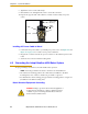
STOP
R
Pendant
(optional)
R
ON
SmartServo IEEE-1394
1 2 3 4
SF ES HD
SW1
1.1 1.2 2.1 2.2
OK
123
XDIO
LANHPE
OFF
XSYS
CAMERA
Eth 10/100
XUSR
Device Net
XFP
RS-232/TERM
RS-232-1
XMCP
BELT ENCODER
SmartController CX
-+ -+
RS-422/485
XDC1 XDC2
24V 5A
*S/N 3562-XXXXX*
RS-232-2