
User`s guide


Chapter 3 - Robot Installation
40 Adept Quattro s650H Robot User’s Guide, Rev A
mounting members, but not the entire frame assembly. Alternate designs should consider
90 Hz as a goal for this part of the frame. Note that this design allows for lengthening the
frame in the direction along the belt travel without significantly changing the natural
frequency.
The robot mounts in four locations, as detailed in the drawings. The holes are tapped for
an M16x2.0 bolt. The Adept Quattro s650H robot may be mounted from the top or bottom
of the frame. A crane or forklift should be used to position the robot. If lifted from above,
the robot must be lifted by user-supplied eyebolts and slings.
Figure 7-1 on page 83 shows the mounting hole pattern for the Adept Quattro s650H robot.
Note the hole location and mounting pad tolerances for position and flatness (Figure 7-8
on page 92).
Deviation from this flatness specification will, over time, cause a possible loss of robot
calibration.
NOTE: Adept suggests welding the robot mounting tabs as a last step in
the frame fabrication, using a flat surface as a datum surface during the
tack welding operation.
Gussets
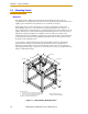
The triangular gussets are an integral part of the frame stiffness. The vibrational strength
of a structural assembly is strongly governed by controlling the shear forces between
members. The 250 mm gussets, shown in Figure 3-3 on page 38, are nominally sufficient
for transferring the load from the vertical members into the horizontal cross pieces.
Preferably, gussets should be placed at the edges of the frame members to transfer the
loading into the walls of the members, instead of the faces, and enable easier cleaning.
Some frame designs may benefit from extending these gussets to 500 mm in the vertical
direction, as the design intent of the gussets is mainly to secure the long vertical members
from rotating out of position. For this reason, the gussets to the across-the-belt horizontal
member should be at the bottom of the member, as shown in Figure 3-3 on page 38, and as
close to the vertical midplane of the frame as feasible (15 mm thickness is adequate for
most situations).
3.6 Mounting the Robot Base
NOTE: All mounting hardware is user-supplied.
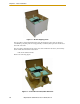
CAUTION: Remove all ancillary components (controller,
outer arms, platform, etc.) from the shipping crate before
lifting the robot base.