
User`s guide

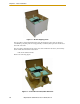

Mounting Frame
Adept Quattro s650H Robot User’s Guide, Rev A 39
NOTE: More specifications for the sample frame are provided in
Section 7.6.
Any robot’s ability to settle to a fixed point in space is governed by the forces, masses, and
accelerations of the robot. Since “every action has an equal and opposite reaction”, these
forces are transmitted to the robot frame and cause the frame and base of the robot to
move and possibly vibrate in space. As the robot system works to position the tool flange
relative to the base of the robot, any frame or base motion will be “unobservable” to the
robot system, and will be transmitted to the tool flange. This transmitted base motion will
result in inertial movement of the tool flange mass, and will cause disturbance forces to be
introduced into the robot control system. These disturbance forces cause “work” to be
done by the robot servo control system which may result in longer settling times for robot
operations.
It is important to note that, even after the system reports the robot to be fully settled, the
tool flange will still be moving by any amount of motion that the suspended base of the
robot may be experiencing.
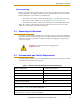
Frame Orientation
The sample robot frame design is stiffer in one direction than the other. This is to
accommodate conveyor belt applications where the robot is moving with much more
acceleration across a conveyor belt than along it. The conveyor should generally be
aligned so that the belt travel is along the robot World Y-axis, and the mid-height frame
members cross the belt at a 90° angle. The across-the-belt dimension of the frame should
be minimized to get the best performance of the robot in that direction. While this frame
design assumes a 1.8 m across-the-belt frame dimension, a 1.5 m dimension would offer
increased stiffness and possibly increased robot performance at high accelerations and
payloads. The mid-height horizontal members are important to the frame stiffness, and
should be located as close to the belt as possible.
For applications requiring high accelerations along the direction of belt travel,
consideration should be given to strengthening the frame in that direction.
Frame Construction
Typically, the frame is constructed of welded steel members. Hygiene-sensitive
applications may call for stainless steel fabrication, with care taken to seal up all possible
voids and grind smooth all weld joints. For other applications, it may be suitable to
manufacture the frame of carbon steel and paint the resulting assembly. The frame design
presented here is based on a stainless steel construction using 10 mm thick members. It
may be reasonable to use a reduced thickness for carbon steel assemblies. Some customers
may choose to use tubular members, or turn horizontal members at 45° angles to facilitate
water runoff from the flat frame surfaces.
Robot-to-Frame Considerations
The Quattro has a moderately-complex mounting requirement due to the nature of the
parallel-arm kinematics and the need to minimize the robot size and mass. Figure 7-5 on
page 86 shows the inner arm travel and how it may encroach on the robot mounting
points. The design suggested here uses transition pieces to allow for butt welds and
mating interfaces where there will be no protruding surfaces to collect contamination.
This mounting design results in a natural frequency of about 90 Hz for just the robot